WBBSE Solutions For Class 10 Physical Science And Environment Chapter 6 Current Electricity

WBBSE Chapter 6 Current Electricity Electric Current, Potential Difference and EMF Concept Of Electric Charge

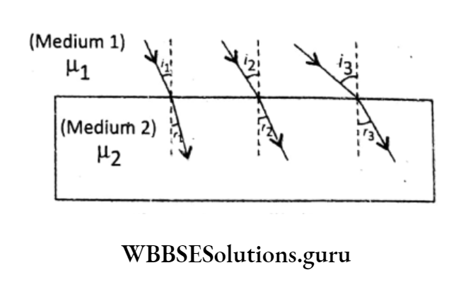
About 600 B.C., in ancient Greece, it was observed that rubbing of two substances acquired some special property of attracting light objects like small pieces of dry paper, light feathers, dry grass, etc. The reason was not known at that time.

A glass rod, rubbing with silk cloth, an ebonite rod rubbing with flannel (cat’s skin), or rubbing a plastic comb against dry hair or a balloon against woolen material, acquire the same kind of attractive properties.

The reason was explained by considering that the substances (comb, wool, balloon, glass, silk, etc.) become electrically charged on rubbing, as they have acquired electric charges.

Then the question arises—What is an electric charge?
Like mass, the charge is a fundamental (intrinsic) part of matter.

WBBSE Notes For Class 10 Physical Science And Environment

Charges exist in two forms— ‘positive’ and ‘negative’.

‘Positive’ and ‘negative’ are just names—used to indicate the existence of two types of charges. This charge convention was decided by Benjamin Franklin.

Each substance contains an equal amount of positive and negative charge. According to modern electronic theory, an atom has an equal number of protons and electrons (showing that an atom is electrically neutral). Charge of \(1 p=+1.6 \times 10^{-19} \mathrm{C} \text { and } 1 \mathrm{e}^{-}=-1.6 \times 10^{-19} \mathrm{C}\)

The transfer of electrons is the only cause responsible for the charging of the bodies.

If an atom gains electrons, it becomes negatively charged; and if an atom loses electrons, it becomes positively charged.

While rubbing two substances, the generated thermal energy initiates to transfer of electrons from one substance to another substance.

Wbbse Class 10 Physical Science Notes

WBBSE Solutions For Class 10 Physical Science And Environment Chapter 6 Current Electricity

This type of electricity is known as static electricity because there is no continuous motion of charges.

According to the law of conservation of charge, the charge can neither be created nor destroyed.

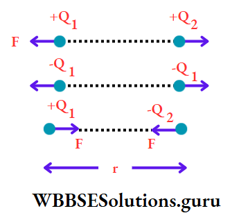
Coulomb’s law: Two like charges (either positive or negative) repel each other and two unlike charges (one positive charge and one negative charge) attract each other with a force known as an electric force.

Scientist Coulomb calculated the magnitude of the electric force acting between two charges. According to Coulomb, this force acts along the line joining two points charges.

Here ‘point charge’ refers to the charge of an object seen from a long distance.

Statement: In a particular medium, the force of attraction or repulsion between two point charges acting along the line joining the charges is directly proportional to the product of the charges and is inversely proportional to the square of the distance between them.

Referring to suppose two point charges and Q2 are separated by a distance. The force acting between the charges is

⇒ \(F \propto Q_1 \cdot Q_2\) (when r is constant) and

⇒ \(F \propto \frac{1}{r^2}\) (When Q1,Q2 are Constant)

WBBSE Notes For Class 10 Geography And EnvironmentWBBSE Notes For Class 10 History And Environment
WBBSE Solutions For Class 10 Life ScienceWBBSE Class 10 Life Science Multiple Choice Questions
WBBSE Solutions for Class 10 MathsWBBSE Class 10 Maths Multiple Choice Questions
WBBSE Notes For Class 10 Physical Science And Environment


Or, F= \(k \cdot \frac{Q_1 Q_2}{r^2}\) (k is a constant of proportionality)

k is not a universal constant. The value of k depends on the nature of the medium. It is different for air, water, oil……..etc.

So the electric force between two point charges Q1,Q2 kept in different media would be \(F_{\text {air }}=\frac{k Q_1 Q_2}{r^2}, \quad F_{\text {water }}=\frac{k^{\prime} Q_1 Q_2}{r^2}, \quad F_{\text {oil }}=\frac{k^{\prime \prime} \mathrm{Q}_1 Q_2}{r^2} \ldots \ldots\)

WBBSE Solutions For Class 10 Physical Science And Environment Chapter 6 Current Elecrticity Forces Of Attraction

Unit of charge: In the SI system, a unit of charge is the coulomb (C) and in the CGS system it is an electrostatic unit (esu) or statcoulomb (state).

Relation: 1 coulomb = 3 × 10⁹ esu Charge.

WBBSE Chapter 6 Current Electricity Electric Potential Difference

An electric field is said to exist around a charged particle within which it can exert an attractive or repulsive force.

Thus, the electric field is associated with each point in space around itself. If a second charge is brought within this electric field, an electric force acts on the charge.

Wbbse Class 10 Physical Science Notes

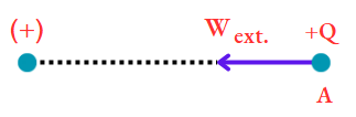
If the second charge is similar to that of the former, then work is to be done by an external agency against electric force.

And, if the charges are dissimilar, then electric force (i.e., attractive force) ownself does the work.

Definition: The amount of work done by an external agency in moving a unit positive charge from infinity to a point within an electric field, without any change of its K.E. is called the electric potential at that point.

WBBSE Solutions For Class 10 Physical Science And Environment Chapter 6 current elecrticity charge of infitify

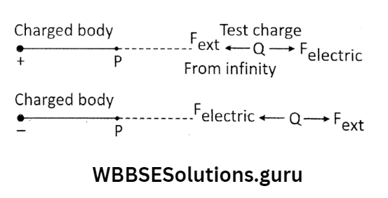
if W amount of work is done in bringing a charge Q.

from infinity to a point P in the vicinity of a positively charged body, then the potential at P is defined as \(v=\frac{W}{Q}.\) [where potential at infinity is assumed to be zero]

This QV amount of work is stored as the electrostatic potential energy within the charge Q.

Both works are done (W) and charge (Q) are scalar quantities so electric potential (V) is also a scalar quantity.

S.l unit of electric potential is volt or V.

From the relation \(\mathrm{V}=\frac{\mathrm{W}}{\mathrm{Q}}, 1 \mathrm{~V}=\frac{1 \mathrm{~J}}{1 \mathrm{C}}=1 \mathrm{~J} / \mathrm{C}\)

What is meant by the electric Potential of a plant being 1 volt?

1 joule of work is done by an external agency in bringing 1 coulomb of charge from infinity to that point.

Potential difference or Voltage: The potential difference (p.d.) between two points is defined as the amount of work done by an external agency in moving a unit positive charge from one point to the other point, without any charge of its K.E.

If W joule of work is done in moving a test charge Q. from point A to point B, then the p.d. between the points is, \(V_B-V_A=\frac{W}{Q}\)

The S.l. unit of potential difference (p.d.) between any two points is a volt.

From the relation,\(\text { p.d. }=\frac{\text { work done }}{\text { charge moved }}\) we obtain, 1 volt = \(=\frac{1 \text { joule }}{1 \text { coulomb }}\)

Thus, if 1 joule of work is done by an external agency in moving 1 coulomb of charge between two points in an electric field, the p.d. between these two points is 1 volt.

Wbbse Class 10 Physical Science Notes

The bigger units of p.d. are kilovolts (KV) and Megavolts (MV). 1KV = 103V and 1MV = 106V.

We are familiar with the term P.E. or potential at a height. For the motion of the ball, a slope or p.d. is required. Similarly, for the flow of charge, a p.d. or voltage is needed.

WBBSE Solutions For Class 10 Physical Science And Environment Chapter 6 Current Elecrticity Potenitial Diffrence Or Voltage

When two charged conductors are either placed in contact or connected by a metallic wire, free electrons flow from the conductor with a higher concentration of electrons (at lower potential) to the conductor with a lower concentration of electrons (at higher potential) till both the conductors have an equal concentration of electrons.

WBBSE Solutions For Class 10 Physical Science And Environment Chapter 6 current elecrticity electric current flow

In fact, this gives rise to electric current flow in the opposite direction of electron flow. If there is no p.d. there will be no current.

This is similar to the flow of heat in two bodies, and the flow of water in two vessels Flow of heat is due to the difference in temperature,

The flow of water is due to the difference in the level of water or hydrostatic pressure.

WBBSE Solutions For Class 10 Physical Science And Environment Chapter 6 current elecrticity lower and higher potenital

WBBSE Chapter 6 Current Electricity EMF And Electrical Cell As Sources Of EMF

We know that for the flow of electric charges through a conductor, a p.d. across its two ends is always needed.

A force is required to set a body in motion. In a similar manner, we can think of a force associated with the motion of charges through an electrical circuit.

Now the question arises -who is pushing/driving the electric charges? This requires a non-electrostatic agency, (like a cell/collection of cells called battery/mains/generator) which is called a source of emf.

Such a source of EMF simply converts some other form of energy into electrical energy.

A cell (or any other electrostatic agency) does not produce charge but maintains a p.d. across its two terminals.

Simply cell is a source of p.d. The word ‘force’ in emf is not used to mean mechanical force (which is measured in Newton) but emf is a potential or energy per unit charge (measured in volts).

That’s why emf can be defined in terms of work done per unit charge.

Definition: Electromotive force (emf) is defined as the amount of work done in establishing the flow of unit positive charge in a closed circuit.

⇒ \(\text { emf }(\varepsilon)=\frac{\text { Work done }}{\text { charge }}\)

Unit of emf \(=\frac{\text { Unit of work done }}{\text { Unit of charge }}=\frac{\mathrm{J}}{\mathrm{C}}=\mathrm{J} / \mathrm{C}=\mathrm{V}\)

This means that the s.l. unit of emf And P.d. is the same volt.

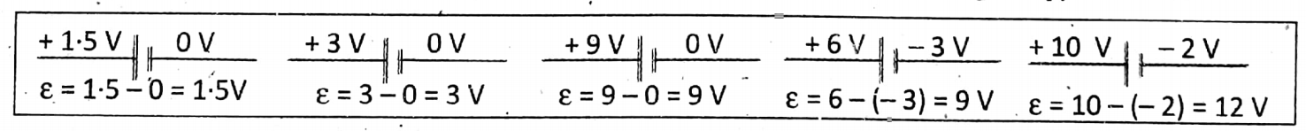
What does the statement ‘The emf of a cell is 1.5 Volt’ mean?

The emf of the cell = 1.5 volt \(=\frac{1.5 \text { joule }}{1 \text { coulomb }}\)

That is, 1-5 joule work is done in moving a charge of 1 coulomb from the positive electrode to the negative electrode of the cell.

WBBSE Chapter 6 Current Electricity Electric Current

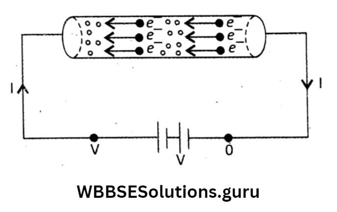
The flow of charges (mainly electrons; because electrons are lighter than protons; also protons are tightly bound with the nucleus) from a body at lower potential (- ve potential) to a body at higher potential (+ ve potential) gives rise to an electric current.

Conventional current flows in the opposite direction of the flow of electrons. In the discussion of current electricity, there is a continuous motion of electrons in the wire.

Electric current is defined as the rate of flow of electric charges through a certain cross-section of conductors.

If Q charge flows through a conductor in time t, then the current is, \(I=\frac{\mathbf{Q}}{\boldsymbol{t}}\)

The S.l. unit of current is coulomb/sec and called ampere (A).

The path along which electric current flows is called an electric circuit.

One ampere is the current that flows through a conductor when one coulomb of charge passes through it in one second.

If n electrons flow through the conductor in time t, then Q = n x e, and the current would be \(1=\frac{n e}{t}\) where e = charge on an electron = \(=-1.6 \times 10^{-19} \mathrm{C}\)

∴1C charge is carried by \(\frac{1}{1.6 \times 10^{-19}}\)  electrons\(=6.25 \times 10^{18}\) electrons.

By the statement “1A current flows through a conductor” we mean that 6.25 × 10¹⁸ electrons flow in 1 second across the conductor.

To express weak current, smaller units of current are used. The smaller units are milli-ampere (mA) and micro-ampere (μA).

They are related to ampere (A) as: \(1 \mathrm{~mA}=10^{-3} \mathrm{~A} \text { and } 1 \mu \mathrm{A}=10^{-6} \mathrm{~A} \text {. }\)

Although electric current flows in a particular direction, it is not a vector quantity-as current and does not obey vector addition rules. It adds up like a scalar quantity.

Wbbse Class 10 Physical Science Solutions

WBBSE Chapter 6 Current Electricity Simple Numerical Problems

Question 1. If 6 coulomb of charge flows through a conductor in 3 seconds, find the strength of the electric current.
Answer: Given: 

Charge (Q) = 6C, time (t) = 3s

Current (I) = \((I)=\frac{\mathrm{Q}}{t}=\frac{6 \mathrm{C}}{3 \mathrm{~s}}=2 \mathrm{~A}\)

Question 2. During how much time, a charge of 20 coulomb flows through a conductor to constitute a current of 4 amperes? 
Answer: Given:

Charge (Q) = 20C, current (I) = 4A

Since Current (I) =\((\mathrm{I})=\frac{\mathrm{Q}}{t} \quad \quad t=\frac{\mathrm{Q}}{\mathrm{I}} \quad \text { or, } \quad t=\frac{20 \mathrm{C}}{4 \mathrm{~A}}=5 \mathrm{~s}\)

Question 3. An electric current of 12 ampere flows through a conductor for 15 seconds. Find the amount of charge that flows.
Answer: Given:

Current (I) = 12A, time (t) = 15s Q

As \(\mathrm{I}=\frac{\mathrm{Q}}{t} \text {, so } \mathrm{Q}=1 \times t \text { or, } \mathrm{Q}=12 \mathrm{~A} \times 15 \mathrm{~s}=1800\)

WBBSE Chapter 6 Current Electricity Ohm’s Law Ohm’s Law Concept Of Resistance

Ohm’s law deals with the relationship between voltage (p.d.) and current in an ideal conductor.

Statement: At a constant temperature, the current flowing through a conductor is directly proportional to the potential difference across the ends of the conductor.

WBBSE Solutions For Class 10 Physical Science And Environment Chapter 6 current elecrticity ohm,s law

Remember that, Ohm’s law is not a fundamental law like Newton’s laws of motion

It is a statement of how voltage and current flowing in a circuit are related to each other, only when the temperature remains constant.

let a current I flow through a conductor when the p.d. across its ends is V, then according to Ohm’s law, \(I \propto V.\) If the current is doubled or tripled voltage will be doubled or tripled.

Similarly, if, the voltage is halved, the current will also be halved. So the reverse relation is also true. Reversing this relation we can get,

⇒ \(V \propto 1\) Or, V = K.l (K= a Proportionality constant) or, \(\frac{V}{\mathrm{l}}=\text { constant }=k\)

If V remains the same then I can increase only if the value of k decreases; the reverse is also true; so that the constant k quantitatively refers to the factor that opposes current.

It is named the resistance of the conductor and it is represented as R.

Thus the Mathematical expression of Ohm’s Law is V=IR

Resistance from Ohm’s law: According to Ohm’s law: V = IR or, R\(=\frac{v}{\mathrm{l}}.\)

That is, at a constant temperature, the ratio of the p.d. across two ends of a conductor.

The unit of resistance is Ohm (Symbol Ω).

⇒ \(1 \text { ohm }=\frac{1 \text { volt }}{1 \text { ampere }}\)

The resistance of a conductor is said to be 1 ohm if 1-ampere current flows through it when a p.d. of 1 volt is applied across its two ends.

The bigger units of resistance are  Kilo-ohm (KΩ²) and Mega-ohm (MΩ)

1KΩ² = 103 Ω² and 1MΩ² = 106 Ω²

Graphical representation of Ohm’s law: If a graph is plotted taking p.d. V along the x-axis and current I along the y-axis, we will get  \(I \propto V \Rightarrow I=\frac{V}{R}\)

The relation is similar to the equation y = mx. So, the l-V graph is a straight line (OA) passing through the origin and its slope is \(=\frac{y-\text { value }}{x-\text { value }}=\frac{1}{R} \text { : }\)

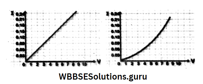
Ohmic conductors: The conductors that obey Ohm’s law are called ohmic conductors, for which the l-V graph is a straight line passing through the origin and the slope of the graph is the same for all values of V and I, that is R is the same, at a given temperature.

Examples: metallic wires.

Non-ohmic conductors: The conductors that do not obey Ohm’s law are called non-ohmic conductors, for which the l-V graph is not a straight line, but a curve, and the ratio V/l is not the same for all values of V and I, that is, R is variable.

Examples: Semiconductors.

WBBSE Solutions For Class 10 Physical Science And Environment Chapter 6 current elecrticity graphical respresation of ohm'slaws

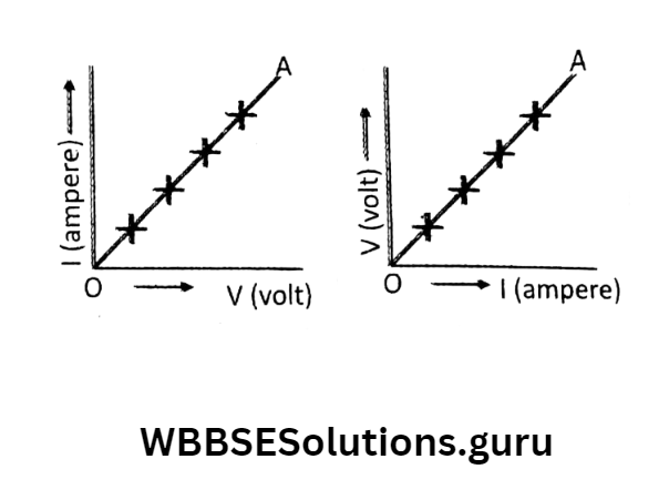
Do all conductors follow Ohm’s law? the p.d. vs current graph for two different conductors A and B. Can you say which conductor has greater resistance?

According to Ohm’s law:  \(V=I R \Rightarrow R=\frac{V}{i}\)

Here, (Slope of A) > (Slope of B) because slope =\(\frac{y-\text { value }}{x-\text { value }}\)

So, A has greater resistance.

WBBSE Solutions For Class 10 Physical Science And Environment Chapter 6 current elecrticity graphical ohmic conductors

WBBSE Chapter 6 Current Electricity Simple Numerical Problems

Question 1. Find the resistance of a wire if 10mA current flows through it and the p.d. across its ends is 2V.
Answer: Given:

Wbbse Class 10 Physical Science Solutions

Current (1) = 10mA = 10×10-3A, P.d (V) =2V

∴ The Value  Of resistance, R = V/1 = \(=\frac{2 \mathrm{~V}}{10 \times 10^{-3} \mathrm{~A}}=200 \mathrm{ohm}\)

Question 2. Two wires have the same terminal p.d. If the ratio of current flowing through them is 1 : 3, calculate the ratio of their Resistances.
Answer:  By Ohm’s Law:
\(I=\frac{V}{R}\)

For the first wire:  \(\mathrm{I}_1=\frac{V}{R_1}\) and for the time second wire: \(\mathrm{I}_2=\frac{V}{R_2}\)

Given: 
\(\frac{\mathrm{I}_1}{\mathrm{I}_2}=\frac{1}{3} \quad \frac{\mathrm{I}_1}{\mathrm{I}_2}=\frac{\mathrm{V}}{\mathrm{R}_1} \times \frac{\mathrm{R}_2}{\mathrm{~V}}=\frac{\mathrm{R}_2}{\mathrm{R}_1}\)

⇒ \(\frac{1}{3}=\frac{R_2}{R_1} \Rightarrow \frac{R_1}{R_2}=\frac{3}{1}\)

⇒ \(\text { i.e. } R_1: R_2=3: 1\)

Question 3. 20V of p.d. across a conductor maintains a current of 0-2A. How much p.d. will be required to maintain a current of 250 mA in the same conductor?
Answer: Given: 

V=20V, I=0.2A, R=?

By ohm’s law: \(\mathrm{R}=\frac{\mathrm{V}}{\mathrm{I}}=\frac{20 \mathrm{~V}}{0 \cdot 2 \mathrm{~A}}=100 \Omega\)

if I= 250 mA =250×10-3A, R=100Ω, then V=?

∴ The required p.d Across the conductor is v=1R=(250×10¯³ A)×(100Ω)=25V

WBBSE Chapter 6 Current Electricity EMF and Internal Resistance of a Cell

EMF of a cell is the potential difference between two terminals of the cell when no current flows i.e. the cell is in an open circuit.

At the time of buying a dry cell from the market, we get the emf value of the cell. But when the cell is connected to an external circuit, it gives a potential difference of less than the EMF value.

Why? Due to internal resistance of the cell (the obstruction offered to current due to electrolytes which act as non-electrical agency).

WBBSE Solutions For Class 10 Physical Science And Environment Chapter 6 current elecrticity internal resistance of the cell

Suppose a cell of emf 8 is connected to an external resistance R and a current I is drawn from the cell.

Under such conditions, the electrolyte inside the cell offers a resistance to the flow of current, known as the internal resistance of the cell denoted as r.

WBBSE Solutions For Class 10 Physical Science And Environment Chapter 6 current elecrticity internal resistance to the demonted r

The connecting wires are considered to have no resistance, so in the circuit, there are two resistances external resistance (R) and internal resistance of the cell (r).

∴ Total Resistance of the circuit  =R+r

∴ Current Drawn From the cell \(I=\frac{\text { e.m.f. of the cell }}{\text { Total resistance }}=\frac{\varepsilon}{R+r}\) Or, ε=V+Ir Or, V=ε-Ir Or, ε=I (R+r) IR+Ir

Here the term ‘IR’ is called terminal voltage (V) or potential difference in the external circuit.

So, the terminal voltage is the potential difference across two terminals of a cell when current is drawn from the cell.

The term ‘Ir’ is the voltage drop inside the cell, called the ‘internal potential drop’ or ‘lost volt’. Because this Ir portion of £ is lost due to the obstruction offered by r.

So we can write: emf of a cell = terminal voltage of the cell + lost volt.

In an open circuit (when no current flows in the circuit): I = 0; Ir = 0; ε = V. That is, the emf of a cell in an open circuit = terminal voltage of the cell.

If R = 0 then V = 0  ε= Ir.

That is, m.f. is just the work done inside a cell by the non-electrical agency, in moving a unit positive charge from the negative terminal to the positive terminal of the cell when there is no external circuit.

WBBSE Chapter 6 Current Electricity Resistivity And Conductivity

We have learned about the resistance of a conductor. Here we will discuss other characteristic properties of conductors.

The factors affecting the resistance of a conductor are—

  1. nature of the material,
  2. length,
  3. area of cross-section and
  4. temperature.

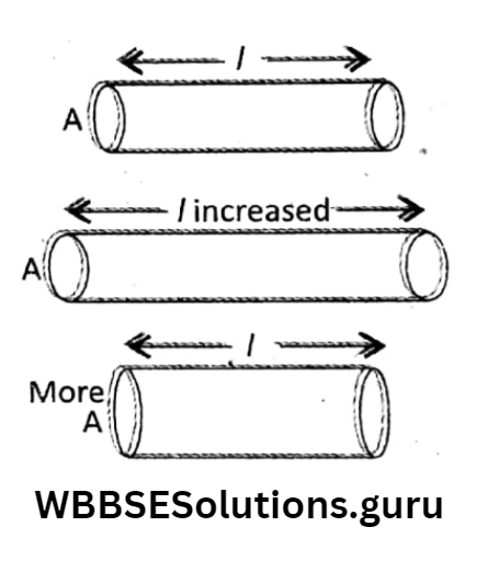
Dependence on length and area of cross-section I (Temperature and nature of material remain same): Suppose we have a conductor of length l and cross-sectional area A.

Its original resistance is R.  1. If l is made to keep the same A, then resistance will also increase.

Thus, resistance is direct R\(\propto\)I (when A remains unchanged).

This means the more the length, the more the resistance, 2. If A is made to increase while keeping the same /, then resistance will decrease. Thus resistance is inversely proportional to area.

Mathematically, \(R \propto \frac{1}{A}\) (when I remain unchanged) is proportional to length. Mathematically, R remains unchanged).

This means, the larger the area, the smaller the resistance. Combining these two or specific we get, \(R \propto \frac{1}{A} \Rightarrow R=\rho \cdot \frac{1}{A} \Rightarrow \rho=\frac{R A}{I}\) resistance of the material of the wire.

In the reaction R=ρI/A, If I=1 and A=1 Then R=ρ. Thus, resistivity is the resistance of a conductor of unit length and unit area of the cross-section at a constant temperature.

Both resistance and resistivity are resistances. Then, what is their difference? Resistance will change with the change of / and A.

But when / and A have unit values, then the resistance is resistivity. If we change the material, we find different p.

So, resistivity is a characteristic property of a material. Resistivity depends on the nature of the material and the temperature of the conductor but not upon the dimensions (/, A).

WBBSE Solutions For Class 10 Physical Science And Environment Chapter 6 current elecrticity resistivity and conductivity

S. I Unit of Resistivity: From the relation R= ρ I/A, We have ρ=RA/I

∴ Unit of ρ =  \(\frac{\text { Unit of } R \times \text { Unit of } A}{\text { Unit of } I}=\frac{\text { ohm } \times \mathrm{m}^2}{\mathrm{~m}}\)

The Statement ‘Resistivity of copper = 1.62×10¯ohm. cm’ means that a Conductor made of copper having a length, equal to

The statement ‘resistivity of copper = 1.62 x 10⁻⁶ ohm. cm’ means that a conductor made of copper having a length, equal to 1 cm and an area of 1 cm2 has a resistance of 1.62 x 10⁻⁶ ohm between its two opposite faces at a particular temperature.

If a wire is stretched to double its length, what will be the change in R and p ? Since the material of the wire remains unchanged, so p will not change. But as R\(\propto\) so R will be doubled.

What would happen to the resistance of a wire if its radius or diameter is 1. doubled and 2. halved?

If r = radius and d = diameter of a write then its area of cross-section is \(A=\pi r^2=\pi\left(\frac{d}{2}\right)^2=\frac{\pi d^2}{4}\).

Resistance of wire \(R=\frac{\rho /}{\pi r^2}=\frac{4 \rho /}{\pi d^2}\)

That is, \(\mathrm{R} \propto 1 / r^2 \text { and } \mathrm{R} \propto 1 / d^2\) (when ρ  and I are fixed)

So, if the radius or diameter of a wire is doubled, its Resistance lessens to 1/4th of its initial value.

If the radius, or diameter of a wire is doubled, its resistance increases to 4 times its initial value.

If a wire is stretched to 3 times its length. Will there be any change in resistivity and resistance? Here resistivity (p) will not change, since the material of the wire remains unchanged.

Here, resistivity (ρ) will not change, since the material of the wire remains unchanged. here,

⇒ \(R_1=\frac{\rho l}{A} \text { and } R_2=\frac{\rho 3 l}{A / 3}=9 \cdot \frac{\rho l}{A}=9 \cdot R_1 \Rightarrow \frac{R_2}{R_1}=9 \Rightarrow R_2=9 R_1 \text {. }\)

Hence, resistance will be 9 times its initial value.

The resistance of a metallic wire increases with an increase in temperature. This is so why a “fixed temperature” is mentioned in defining resistivity.

Electrical conductivity: Just like resistance in a conductor there is another factor known as conductance (G).

Reciprocal resistance is called \(\left(\frac{1}{R}\right)\)conductivitance. The \(\sigma=\frac{1}{\rho}=\frac{1}{\mathrm{RA}}\)reciprocal of resistivity is called the electrical conductivity.

It is represented as a property of the conductor whereas ρ is a property of the non-conductor/ insulator. A good Conductor should have a high value of σ and a low value of ρ.

Units of electrical conductivity: In S.l. the system, ohm-1.m-1 or mho.m-1 or S.m-1, and CGS system, ohm-1.cm-1 or mho.cm-1.

Conductors and Insulators: Substances with low resistivity and high electrical conductivity are good conductors. They allow an electric current to flow easily.

Most metals (Ag, Cu, Al ….) are good conductors. On the other hand, insulators have very high resistivity and their electrical conductivity is very low (almost nil).

Examples— are wood, rubber, plastic, etc. Insulators are mainly used to protect us from electrical shock because of their poor electrical conductivity.

Resistivity is a more fundamental property as compared to resistance. Because the resistance of wire changes with the change of its length and area of cross-section; the resistivity remains unchanged for such changes.

Resistivity depends on oh temperature,

For metals, resistivity increases with the increase in temperature, and For semiconductors, it decreases with the increase in temperature.

For alloys, it remains nearly unaffected by the change in temperature. For example, the resistivity of constant (Cu + Ni), and manganin (Cu + Mn + Ni) remains almost constant with the rise in temperature.

WBBSE Solutions For Class 10 Physical Science And Environment Chapter 6 current elecrticity before and after stetching

Represents the resistivity of some substances. The values of resistivity help us to recognize conductors, semiconductors, and insulators separately.

Resistivity depends on the material of the substance, For metals, it is very low (-10-8Ω.m), for semiconductors, it is low (-10-5Ω.m) and for insulators, it is very high (-10-13Ω.m).

For electrical connections and power transmission, the wires used should possess negligible resistance and very small resistivity.

Copper or aluminum possesses such qualities. This is the fact why the wires are generally made of copper or aluminum.

Generally, the standard resistors are made from alloys, such as manganin, constant, nichrome, etc. These are so chosen as their resistivity remains practically constant with the change in temperature.

The filament of a bulb is made by using tungsten. Because it has-

  1. High melting point and
  2. High resistivity.

The resistance of the tungsten filament of a bulb is more when it is glowing as compared to when it is not glowing.

This is so because in the glowing condition, the filament is at a high temperature, and for it, the resistance increases.

The resistivity of an alloy is more than that of its constituent metal. For example, the resistivity of the constant (Cu + Ni) is nearly 30 times more than that of Cu.

The heating element of the heater is made by using a nichrome (Ni + Cr + Fe) wire because of its high resistivity.

A fuse wire is made from an alloy of lead and tin in a ratio: of 1. Because it has a low melting point and high resistivity.

Superconductor: Generally, the resistivity of metals decreases with the decrease in temperature.

There is a category of substance whose resistivity becomes almost zero at a lower temperature less than a particular value, called critical temperature and this type of substance is called superconductor.

For example, mercury below 4-2K behaves as a superconductor. Superconductors have infinite conductivity.

Resistivity-temperature graph: the resistivity-temperature graph.

The utility of the graph is to identify the metallic conductors, semiconductors, and superconductors on the basis of the variations of their resistivity with different temperatures.

WBBSE Solutions For Class 10 Physical Science And Environment Chapter 6 current elecrticity super conductor

WBBSE Chapter 6 Current Electricity Series And Parallel Combination Of Resistances

Sometimes two or more resistances are connected together to make a combination of resistances for different purposes in electric circuits.

WBBSE Solutions For Class 10 Physical Science And Environment Chapter 6 current elecrticity series combitination


There are two ways of a combination of resistances—

  1. series combination and
  2. parallel combination.

Series combination:

Two resistances R1 and R2 are connected in series (end-to-end). In this combination, let us look at the p.d. across each resistance and the current flowing through them.

Since the resistances are connected end-to-end, the same current (suppose I, the main current) flows through each resistance.

If V is the supplied p.d. of the battery then V is divided into two parts V1 and V2 across R1 and R2 respectively V= V1 + V2.

According to Ohm’s law: V1 = \(l_1=\frac{V}{R_1}\) and V2 = \(l_2=\frac{V}{R_2}.\)

If Rs be the equivalent resistance of this series circuit, then V = \(l_s=\frac{V}{R_s}\)

Since l = l1 + l2

∴ \(\frac{V}{R_p}=\frac{V}{R_1}+\frac{V}{R_2} \Rightarrow \frac{1}{R_p}=\frac{1}{R_1}+\frac{1}{R_2}\)

If three resistances R1,R2 And R2 are connected in series then \(\frac{1}{R_p}=\frac{1}{R_1}+\frac{1}{R_2}+\frac{1}{R_3}\)

In a series combination, the equivalent resistance is more than the highest value of the resistance connected.

But in a parallel combination, the equivalent resistance is less than even the smallest resistance connected.

That is Rs >R1 R2, R3, … and Rp <R1 R2,R3,…….

In series combination, p.d. gets divided but the same current flows through each resistance. In

parallel combination, p.d. remains the same across the resistances but the current gets divided.

When the resistance of the combination is to be increased, the series combination is preferred, and when the resistance is to be reduced,

i.e., if more current is to pass through the circuit, the parallel combination is preferred.

WBBSE Solutions For Class 10 Physical Science And Environment Chapter 6 current elecrticity parallel combination.2

WBBSE Chapter 6 Current Electricity Simple Numerical Problems

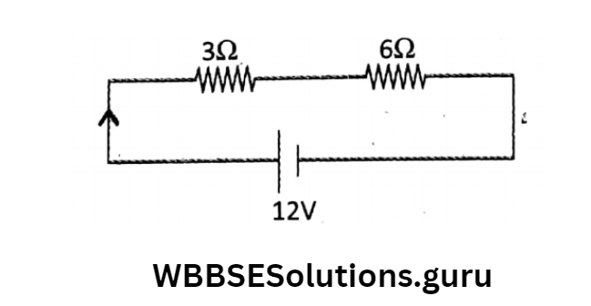
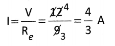
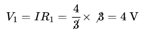
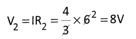
Question 1. Two resistances 3Ω and 6Ω are connected in (1) series and (2) parallel with a supply voltage of 12V. Draw the circuit diagrams. Then find a current and potential drops in all resistances.
Answer: (1) Series Combination 

WBBSE Solutions For Class 10 Physical Science And Environment Chapter 6 current elecrticity series combitination

Here Equivalent resistance,

Re = R1 + R2= 3+6= 9Ω

Current Flows Through each resistance,

WBBSE Solutions For Class 10 Physical Science And Environment Chapter 6 current elecrticity series combination 1

The potential drop in 3Ω,

WBBSE Solutions For Class 10 Physical Science And Environment Chapter 6 current elecrticity series combination 3

The potential drop in 6Ω,

WBBSE Solutions For Class 10 Physical Science And Environment Chapter 6 current elecrticity series combination 2

Wbbse Class 10 Physical Science Solutions

(2) Parallel Combination 

WBBSE Solutions For Class 10 Physical Science And Environment Chapter 6 current elecrticity parallel combination.3

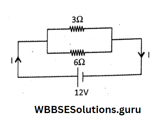
⇒ \(\frac{1}{R_e}=\frac{1}{R_1}+\frac{1}{R_2}=\frac{1}{3}+\frac{1}{6}=\frac{2+1}{6}=\frac{3}{6}=\frac{1}{2}\)

Re=2Ω

Main Current, \(\mathrm{I}=\frac{\mathrm{V}}{\mathrm{R}_e}=\frac{12}{2}=6 \mathrm{~A}\)

⇒ \(l_1=\frac{V}{R_1}=\frac{12}{3}=4 \mathrm{~A} \text { and } I_2=\frac{V}{R_2}=\frac{12}{6}=2 \mathrm{~A}\)

Potential Drop across 3Ω and 6Ω resistance is the same = 12 V.

Wbbse Class 10 Physical Science Solutions

Question 2. What will be the equivalent resistance of the combination of resistors 1Ω, 10Ω, and 100Ω (1) in series combination and (2) in parallel combination?

(1) The equivalent resistance in a series combination

Rs = 1Ω+10Ω+100Ω=111Ω

(2) The equivalent resistance in parallel combination

⇒ \(\frac{1}{\mathrm{R}_p}=\frac{1}{1}+\frac{1}{10}+\frac{1}{100}=\frac{100+10+1}{100}=\frac{111}{100}=0 \cdot 9 \Omega\)

Activity: We make two circuits Two identical bulbs are connected (1) in series (end-to-end) and (2) in parallel combination (between two common points).

We are to compare how the brightness of each bulb varies in the two combinations. Here the bulbs act as resistors since the resistance of the connecting wire is neglected.

In a series combination, the same current flows through each bulb, while the equivalent resistance becomes more than either of the two resistances.

So, the electric current becomes less, and as a result of which, bulbs glow dimly, and the brightness of each bulb diminishes.

In parallel combination, each of the two bulbs is connected across the two ends of a cell. The equivalent resistance of this combination becomes lower than either of the three resistances.

So, the electric current becomes more. The current in each bulb remains unaffected by the presence of another bulb.

So, the bulbs glow as bright as they were connected individually to the supply voltage.

Due to this fact, in your house bulbs/fans/TV/computer, etc. all are connected in parallel combination with the supply voltage.

WBBSE Solutions For Class 10 Physical Science And Environment Chapter 6 current elecrticity bulbs glow dimly and brightness of each bulb diminishes

WBBSE Chapter 6 Current Electricity Heating Effect Of Electric Current Joule’s Law of Heating Effect Of Current Concept Of Electrical Energy

When an electric current flows through a conductor in any direction, it gets heated up and this fact is known as the heating effect of current.

Why this heating effect is happening?  Whenever a conductor is connected to a voltage source, the electrons present in the conductor start moving towards the higher potential (+ ve terminal of the battery).

During this movement, electrons collide with atoms, ions, etc. present in the conductor.

As a result of which, electrons have to overcome the resistance of the conductor, and a loss of energy of electrons takes place.

WBBSE Solutions For Class 10 Physical Science And Environment Chapter 6 current elecrticity heating effect of current

This energy gets converted into heat energy for which the heating of the conductor takes place.

The heating effect of current plays an important role in home appliances like electric kettles, electric stoves, electric irons, electric cookers, etc.

Whenever you keep your mobile connected to a charger for a long time or when you watch TV for a long time while touching your mobile/TV you feel hot; even a fan or every electronic gadget gets hot.

Mathematics: Suppose a p.d. V is applied across a conductor. Here, the cell is not producing charge it only gives energy to electric charge.

Thus, the cell does some electrical work.

⇒ \(\mathrm{V}-0=\frac{\mathrm{W}_{\text {ext.agency }}}{\mathrm{Q}}=\frac{\mathrm{W}_{\text {done by cell }}}{\mathrm{Q}} \Rightarrow \mathrm{W}_{\text {done by cell }}=\mathrm{E}_{\text {supplied by cell }}=\mathrm{VQ} \ldots \ldots . \text { (i) }\)

Suppose the cell allows I current to flow through a resistance R  of the Conductor for time t. Then the amount of charge flown in time t will be \(1=\frac{Q}{t} \quad Q=I t\)

Using the value of ‘Q’ From (2) Into (1):  W=V×I×t……….(3)

According to Ohm’s Law: V= IR. So that W= IR×I×t⇒ W= I²Rt…………(4)

Again using Ohm’s Law: \(I=\frac{V}{R}.\) Then \(\mathrm{W}=\frac{\mathrm{V}^2}{\mathrm{R}^2} \times \mathrm{R} \times t \Rightarrow \mathrm{W}=\frac{\mathrm{V}^2}{\mathrm{R}} t\)…………………(5)

This work appears as the heat energy in the conductor.

From the work-heat equivalence of heat\(W=J H \Rightarrow H=\frac{W}{J}\) (as stated in class IX), relations (3), (4).and (5) can be expressed in terms of heat produced.

We know that J = 1 in the SI system and J = 4-2 joule/cal in the CGS system. So the relations for heat produced in a conductor are

H= \(\mathrm{VIt}(\mathrm{SI}) \text { and } \mathrm{H}=\frac{\mathrm{VIt}}{4 \cdot 2} \mathrm{cal}(\mathrm{CGS})\)

H = \(\mathrm{I}^2 \mathrm{R} t(\mathrm{SI}) \text { and } \cdot \mathrm{H}=\frac{\mathrm{I}^2 \mathrm{R} t}{4 \cdot 2} \mathrm{cal}(\mathrm{CGS})\)

H= \(\frac{\mathrm{V}^2}{\mathrm{R}} t(\mathrm{SI}) \text { and } \mathrm{H}=\frac{1}{4 \cdot 2} \cdot \frac{\mathrm{V}^2}{\mathrm{R}} t \mathrm{cal} \text { (CGS) }\)

These relations are known as Joule’s law of the heating effect of the current

According to this equation:

⇒ \(H \propto R\)(R, t constant),

⇒ \(H \propto R\)(I, t constant) and

⇒ \(H \propto t\)(I, R constant)

Joule’s laws of heating effect of current: There are three laws.

First Law: The amount of heat H produced in a conductor is directly proportional to the square of the current (I) flowing through it when resistance and time of flow of current remain the same, i.e. \(\mathbf{H} \propto \mathbf{I}^2\) (When R and t remain constant)

Second Law: The amount of heat H produced in the conductor is directly proportional to the resistance R of the conductor when the current and time of flow of current remain the same, i.e.,  \(H \propto R\)(When I and t remain constant),

Third Law: The amount of heat H produced in the conductor is directly proportional to the time of flow t of current when current and resistance remain the same, i.e., \(H \propto R\) (When I and R remain constant)

WBBSE Chapter 6 Current Electricity Domestic Uses Of Heating Effect Of Current

The common household electrical appliances which make use of the heating effect of current are electric heaters, irons, bulbs, geysers, toasters, ovens, immersion heaters, etc.

Electric heater: The heating coil in an electric heater is made of nichrome (an alloy of 60% Nickel, 25% iron, and 15% chromium) wire (it is also called a heating element).

  1. Because nichrome
  2. Has a high resistivity,
  3. A high melting point, and

Does not get oxidized up to a temperature of about 1000°C. The nichrome wire is wound in the form of a helical coil and placed in some insulating material (it protects the user from electric shock).

When an electric current passes through the coil, it becomes very hot.

Electric iron: Electric iron is used for pressing clothes. The heating element in iron is a flat nichrome coil wound on a mica sheet.

The coil is made flat so that the heat spreads over a large surface area. When an electric current passes through the heating element, it produces heat energy.

Electric bulb An incandescent electric bulb consists of a very fine coil of tungsten. Tungsten has a Very high resistivity,

Wbbse Class 10 Physical Science Notes

The very high melting point of about 3300°C. The bulb is filled with argon gas at very low pressure and completely evacuated.

When an electric current is passed through this, the filament gets heated up and it emits heat energy and light energy. This is due to the heating effect of the current.

WBBSE Solutions For Class 10 Physical Science And Environment Chapter 6 current elecrticity domestic usages of electronics of current

Fuse or cut-out: The fuse is a safety device in an electric circuit. It protects electric circuits and electrical appliances by stopping the flow of electric current.

Wbbse Class 10 Physical Science Notes

The material of the fuse wire is made from an alloy of lead and tin in a ratio 3: of 1. It has

  1. A low melting point and
  2. A high value of resistance.

When the circuit becomes overloaded due to short-circuiting or fluctuation of current /the fuse melts and breaks the circuit and thus the electrical appliances are saved.

When the live wire and the neutral wire come in direct contact, it is called a short circuit.

Wbbse Class 10 Physical Science Notes

The fuse is always connected to the live wire in an electric circuit, at the point where current enters the circuit.

If the fuse is connected to the neutral wire, it will melt when there is overloading. Under such conditions, if an electrical appliance is touched, even in the OFF position, the person will get a shock as the appliance is connected to the live wire.

Wbbse Class 10 Physical Science Notes

To protect electric appliances like T. V. sets, Refrigerators, geysers, Iron, mixers, etc. cartridge fuses are used. These are fixed within the appliance.

Such fuses have a maximum tolerance current.

To protect a circuit, the fuse should be of a lower value of current than the maximum current that the circuit can withstand. Fuse ratings (e.g. 5A, 10A, 15A, ) ensure it.

For example, a 5A fuse can withstand a maximum of 5A current. If a current of more than 5A flows, the fuse melts.

These days, the use of MCB or Miniature Circuit Breaker Mechanical Circuit Breaker is very popular rather than traditional fuses.

It is used to protect each individual circuit; If the circuit is overloaded, the MCB falls down to switch off the circuit without causing damage.

Wbbse Class 10 Physical Science Notes

WBBSE Solutions For Class 10 Physical Science And Environment Chapter 6 current elecrticity electrical fuse and MCB

WBBSE Chapter 6 Current Electricity Electrical Power

In Physics, power is defined as the rate of doing work. So, Electrical power is defined as the rate of doing electrical work or the amount of electrical work done in 1 second. Mathematically

Wbbse Class 10 Physical Science Notes

P\(\frac{\text { Electric work done or energy supplied by the cell }}{\text { time }}=\frac{W}{t} \text { or, } \frac{E}{t}\)

But, \(\text { But, } W=V I t \quad P=\frac{V I t}{t}=V I \quad P=\frac{I^2 R t}{t}=I^2 R\)

P=\(\frac{V^2}{R^2} \times R=\frac{V^2}{R} \text { for fixed } V \text {. }\)

Any relation can be used to calculate electrical power.

Remember: Electrical power is supplied by a cell or any other voltage source and power is always dissipated in a resistor, across which the source is connected.

The S.I. unit of electrical power is the watt (or W). Bigger units of power are kilowatts (KW), and megawatt MW where 1 kW = 10³ W and 1 MW = 106W.

Electrical power is said to be 1 watt when 1 joule of electrical work is done in 1 second, Or, the cell supplies 1 joule of energy in 1 second to the electric charge.

Units of electrical energy: An electrical bill is prepared on the basis of the amount of electrical energy (E) consumed in our homes/schools/industries.

The basic formula is E = P x t i.e. electrical energy consumed = electrical power x time. The commercial unit of electrical energy is watt-hour (W-h) and kilowatt-hour (kW-h).

1 watt-hour = 1 watt x 1 hour = 1 watt x 3600s = 3600 joule.

1 kilowatt-hour = 1 kilowatt x l hour = 100 Js-1 x 3600s = 3-6 x 106 = 3.6 MJ.

B. O. T. (or Board of Trade) unit: The bigger unit of electric energy is a kilowatt-hour. It is also known as B.O.T.

(Board of Trade Unit), which is the electric energy spent by an electric appliance of power 1 kilowatt used for 1 hour.

⇒ \(1 \text { B.O.T. unit }=1 \mathrm{kWh}=\frac{\text { watt } \times \mathrm{h}}{1000}=\frac{\text { volt } \times \text { ampere } \times \mathrm{h}}{1000}\)

WBBSE Chapter 6 Current Electricity Simple Numerical Problems

Question 1. A battery of 12V supplies a 2A current. Calculate its power.
Answer: Given: V = 12V, I = 2A So, power supplied by the battery P = V x l = 12 x 2 = 24 watt = 24 J/s.

Question 2. A torch bulb of 4-5V draws a current of 0-3A. If the bulb is switched on for 10 minutes, find out the energy released by the bulb.
Answer: Given: V – 4.5V, I = 0.3A, t = 10 min = 600s

The energy released by the bulb, E = Vlt = 4-5 x 0-3 x 600 = 810J

Question 3. An electric bulb of resistance of 500Q draws a current of 0.4A. Calculate its power.
Answer: Given: R = 5000, I = 0.4A, P = ?

Electric power P = l²R = (0-4)²x 500 = 80 watt

Wbbse Class 10 Physical Science Solutions

Question 4. A family uses one 100W bulb, one 100W fan, and one 1000W heater for 8h daily. Calculate the daily household electric bill, if one unit costs Rs. 3-00.?
Answer: The electrical energy consumed per day is

⇒ \(=\frac{\text { watt } \times h}{1000}=\frac{(1 \times 100+1 \times 100+1 \times 1000) \times 8}{1000}=9.6\)

Daily electric bill costs = Rs. 3.00 x 9.6 = Rs. 28.80.

Question 5. Two electric bulbs of 100W and three electric fans of 60W are used daily for 5 hours. What will be the cost for it in one month (30 days)? The cost of each unit is Rs. 3.50.
Answer:  The electrical energy consumed per day is

⇒  \(=\frac{\text { watt } \times h}{1000}=\frac{2 \times 100 \times 5+3 \times 60 \times 5}{1000}=1.9\)

The total electrical energy consumed in 30 days =1.9×30=57

∴ The cost of it is = Rs. 3.50 × 57 = Rs.199.50

If The Bulb is Connected To a p.d. less than 220V (say 110V), the build will consume less power and will glow dimly.

Then power Consumed will be, \(P=\frac{V^2}{R}=\frac{(110)^2}{484}=25 \mathrm{~W}\)

Rating And Its Significance: 

  • In general, electrical appliances such as electric bulbs, irons, heaters, geysers, washing machines, etc. are rated by their power and voltage.
  • This is known as power-voltage rating or simply power rating. This power rating is done to calculate
  • The resistance of the appliance and
  • The safe limit of current that can pass through it.

For example, an electric bulb rated as 100W, 220V means that when the bulb is connected to a 220V main line, it glows fully and consumes 100W power or 100J of electrical energy in 1 second.

While glowing the resistance of the filament of the bulb is, \(R=\frac{V^2}{P}=\frac{(220)^2}{100}=484 \Omega\)

The safe limit of current that flows in the Bulb is \(I=\frac{P}{V}=\frac{100}{220}=0.45 \text { (approx) }\)

  • Three different types of light bulbs are available in the market. These are Incandescent bulbs, CFL (Compact fluorescent lamps), and LED (Light Emitting Diode).
  • CFL and LED are more efficient than incandescent bulbs from the point of the energy economy. Incandescent bulbs contain tungsten filaments.
  • When an electric current is passed the filament gets heated up and emits light. More than 95% of the energy gets converted into heat energy.
  • Only less than 5% of the energy is converted into light energy. That’s why an incandescent bulb becomes hot when switched on.

A CFL contains argon and a small amount of mercury vapor when a current is passed, this generates UV light and excites the fluorescent coating inside the bulb which produces visible light.

  • On the other hand, LEDs are semiconductors.
  • When current (i.e. electrons) is passed, they emit light. Out of these three, LED is better than others.
  • CFL is not eco-friendly like LED, because CFL contains toxic mercury vapors.

WBBSE Solutions For Class 10 Physical Science And Environment Chapter 6 current elecrticity led bulb and CFL bulbSignificance of the energy rating mark given in household electrical appliances: The Bureau of Energy Efficiency (BEE) under Govt, of India, suggests marking the energy star level of household electrical appliances, such that, 5 stars (*) appliances save maximum energy while 1-star (*) appliances save the least energy.

From the point of the energy economy, a buyer should use 5-star appliances to save on electricity bills.

Activity:

(1)Value development against misuse of electrical energy: We are all aware of today’s energy crisis, lack of fossil fuels, load shedding scenario, along needless misuse of electricity at homes, schools, government offices, etc.

The best thing to do for us is to minimize wastage. It requires common people’s awareness. Government-level initiatives are also required.

These days more efficient CFL and LED bulbs are available. Although these are expensive, they are 4-6 times more efficient than filament-based bulbs, They are useful against misuse of electrical energy.

An incandescent bulb of power 100 W has the same brightness as a CFL bulb of power 24 W and an LED bulb of 16 W.

(2) Suppose two bulbs rated as SOW and 100W are connected in series and in parallel with the same voltage line. In the two cases which bulb glows more brightly than the other?

1. In a series of connections between the bulbs, the same current flows through each bulb. That is,

I= Constant. As\(P=V^2 / R, \text { so } P \propto \frac{1}{R}\) for the same V i.e. resistance of 60 W bulb is more than the 100W bulb.

As \(P=1^2 R \text {, so } P \propto R \text {. }\) Hence, the 60W bulb glows more brightly.

2. In parallel connection of the bulbs, the current in each of them does not remain the same (although the p.d. V remains constant).

Remember: Resistance of a Particular build remains the same as \(R=\rho \frac{1}{A}. \text { As } P=\frac{V^2}{R}\) \(P \propto \frac{1}{R} .\) Thus, for the same v, the 100W bulb glows more brightly.

WBBSE Chapter 6 Current Electricity Electromagnetism Action Of Electric Current On Magnet

Magnetism has been known since ancient times and electricity has been discovered in the 1700s. Until 1820, electricity and magnetism were studied as two separate branches.

Electricity was considered a phenomenon related to electric current, while magnetism was considered to be related to magnets.

In 1820, famous physicist Hans Christian Oersted first experimentally proved that a current-carrying wire behaves like a magnet, or a current-carrying wire produces a magnetic field around itself as long as the current is passed through it.

This is known as the magnetic effect of electric current. Oerested proved that electricity and magnetism are related to one another.

Today we have a new branch of study known as electromagnetism.

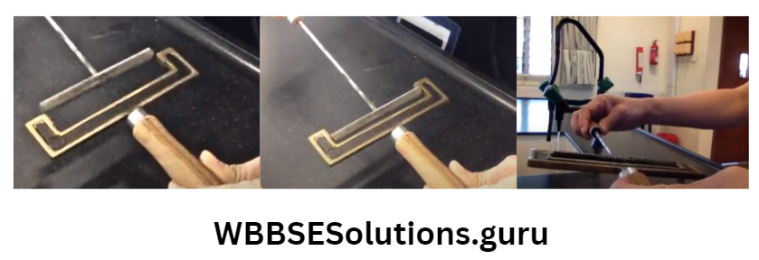
Activity: Oersted’s experiment: Materials required: A magnetic compass (tiny magnet), Cu wire, battery with crocodile clips, and a few carrom coins.

Procedure: Fix carrom coins on a table with the help of glue tape over which stick the Cu wire. Place the magnetic compass below the Cu wire.

At this position, the magnetic compass needle points in a geographical north-south direction.

Then connect the H-Ve and -Ve terminals of the battery with two ends of Cu wire and allow current to flow.

Observations: The compass needle at once gets deflected to one side deflection towards the East). A magnet can only influence another magnet.

So we can say that a current-carrying wire exerts a force on a magnet.

If the amount of current is increased, then the magnetic compass shows a larger deflection.
So, the magnetic field produced in the wire is directly proportional to the electric current.

Current is passed through the Cu wire and the compass is taken slightly away from the Cu wire. The deflection of the magnetic needle decreases the Greater the distance weaker the magnetic field.

Place the compass above the wire. The magnetic needle deflects in the opposite direction (deflection towards the west).

As if the direction of the electric current is reversed, the direction of deflection of the magnetic needle gets reversed.

So we can say that the direction of the magnetic field can be reversed by reversing the direction of the current flow.

Rules for determining the direction of deflection of magnetic needle: The direction of deflection of the magnetic needle due to current can be determined by any one of the following two rules:

1. Ampere’s swimming rule: If a swimmer stretching his arm is swimming along a current carrying wire in the direction of the current, facing the magnetic needle, then the direction in which the left hand of the swimmer points gives the direction of deflection of the north pole of the magnetic needle

WBBSE Solutions For Class 10 Physical Science And Environment Chapter 6 current elecrticity Ampere's swimming rule

Explanation on the basis of observation of Oerested’s experiment: Suppose the wire is placed over the compass through which current flowing from S→N due to which [following SNOW Rule (S: South, N: North, O: Over and W: West – Where anyone change of S/N/ O/W, deflection of N-pole will be changed to either E or W and for two changes deflection will be a pole of the magnetic compass will be deflected towards West.

WBBSE Solutions For Class 10 Physical Science And Environment Chapter 6 current elecrticity Snow

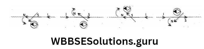
2. Wire is over the compass and current flowing from N→ S for which [following NSOE Rule] N-pole of the magnetic compass will be deflected towards East,

3. Wire is placed below the compass and current flows from S to N for which N-pole will be deflected towards East [following SNBE Ruie.]

4. (following NSBW Rule) N-pole will be deflected towards the West. (As a whole this rule is very complex).

Right-hand grasp rule: If we hold a current-carrying conductor in the right hand such that the thumb points in the direction of flow of current, then the direction in which other fingers curl/wrap gives the direction of the magnetic field.

WBBSE Solutions For Class 10 Physical Science And Environment Chapter 6 current elecrticity right hand grasp rule

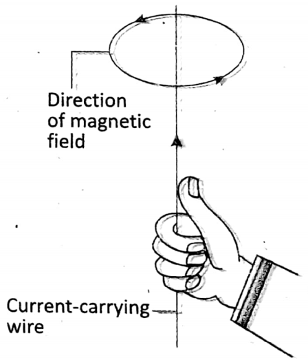
Explanation: According to the right-hand grasp rule, keeping the thumb towards the direction of current, the direction along which other fingers curl for gripping the wire, produces a circular path.

For which the current is flowing in an upward direction and for which the current is flowing in a downward direction.

This circular path gives the direction of the magnetic field produced due to current this is the direction along which a north pole moves. [This rule is easier).

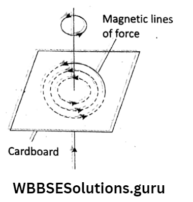
Magnetic field around a long straight wire: A straight wire passes vertically through a hole made at the center of the cardboard. Some iron filings are sprinkled on the cardboard.

A current is passed through the wire in an upward direction and the cardboard is gently tapped. The iron filings get arranged along some concentric circles around the wire.

The arrows show the direction of the magnetic field. It is observed that a straight current-carrying wire produces a magnetic field that looks like concentric circles around the wire.

Here, the magnetic field strength is very weak.

Magnetic field around a circular wire: A straight wire is bent into a circular loop. The loop passes through two points on cardboard.

Some iron filings are sprinkled on the cardboard. A current is passed through the loop and the cardboard is gently tapped.

Shows that the iron filings get arranged along two sets of concentric circles for each end of the wire.

WBBSE Solutions For Class 10 Physical Science And Environment Chapter 6 current elecrticity magnetic field around a long straight wire

The arrows show the direction of the magnetic field. The magnetic field of a circular loop is stronger than a straight wire.

How? Imagine the loop is divided into small segments which are nearly straight wires. Each straight segment produces a magnetic field in the shape of concentric circles.

WBBSE Solutions For Class 10 Physical Science And Environment Chapter 6 current elecrticity Direction of current

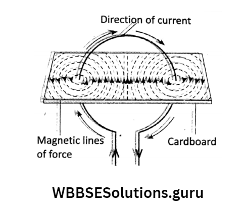
At the center of the loop, the magnetic field lines are almost straight and they add up which the magnetic field becomes stronger.

If instead of one loop, there are N loops then the magnetic field will be N times stronger.

The similarity between a field due to a magnetic pole and a field due to a circular current-carrying loop:

In a circular current-carrying loop, the magnetic field lines at the center, are along the axis of the loop and normal to the plane of the loop.

If the loop is replaced by a thin magnet, similar types of magnetic field lines will be obtained. That is, the behavior of a current-carrying loop is similar to that of a magnetic pole.

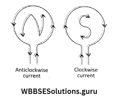
Polarities in a current-carrying loop: If you look at the face of the loop and assume that the current flows in an anticlockwise direction then the face of the loop acts as a north pole and for the flow of current in a clockwise direction, the loop acts as a south pole.

WBBSE Solutions For Class 10 Physical Science And Environment Chapter 6 current elecrticity clock and anti clock wise

WBBSE Chapter 6 Current Electricity Action Of Magnet On Current

We learned that a current-carrying wire exerts a force on a magnet. Is the reverse also true? Can a magnet exert a force on a current-carrying wire?

In 1821 Michael Faraday experimentally observed that whenever a current-carrying wire is placed in a magnetic field the current-carrying wire experiences a mechanical force acting on it which is known as a magnetic force.

If there is no current in the wire, there is no force. If the wire is free to move, it will produce motion wire.

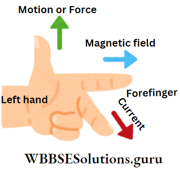
This is known as the action of a magnet on current. The direction of force or motion of the conductor can be found by Fleming’s left-hand rule.

Fleming’s left-hand rule: Stretch the first three fingers of the left hand mutually perpendicular to each other such that if the forefinger indicates the direction of the magnetic field and the middle finger indicates the direction of current, then the thumb will indicate the direction of force or motion of the conductor.

WBBSE Solutions For Class 10 Physical Science And Environment Chapter 6 current elecrticity magnetic flemings left hand rule

Principle of working of Barlow’s wheel: Whenever an electric conductor is brought in a magnetic field, the conductor gets motion due to the presence of the magnetic field. One such example is Barlow’s wheel.

It is a suitable instrument that shows how motion is produced in a current-carrying conductor placed in a magnetic field. In it, electrical energy is converted into mechanical energy.

The direction of rotation of the wheel can be determined by applying Fleming’s left-hand rule.
Barlow’s wheel consists of a star-shaped copper wheel, capable of rotating freely in a vertical plane about a horizontal axis.

A pool of mercury is kept in a small groove on the wooden base of the apparatus such that the point of each spoke of the wheel just dips into the pool of mercury while rotating.

The pool of mercury is kept in between the NS poles of a strong magnet When the axis of the wheel and the mercury are connected to a battery, the circuit is completed and the wheel starts rotating due to the action of the magnet on the current.

While rotating, when a spoke of the wheel just leaves mercury, the circuit breaks out, but due to inertia of motion, the next spoke comes in contact with mercury, thereby rotation of the wheel continues.

The speed of rotation of Barlow’s wheel depends upon the—

  1. The strength of the magnetic field, and
  2. The strength of the current.

WBBSE Solutions For Class 10 Physical Science And Environment Chapter 6 current elecrticity barlows wheel

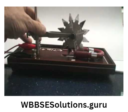
The rotation of Barlow’s wheel increases with increasing the current. The wheel rotates in the opposite direction when the current is reversed.

The rotation of Barlow’s wheel is possible in D. C. only, but not in A.C.

Reason: In A. C., the direction of rotation of the wheel changes its direction during each half-cycle. Ultimately, no rotation of the wheel is possible in A.C.

WBBSE Chapter 6 Current Electricity Electric motor

What makes an electric fan move? Electric motor. In many instruments like tulle pumps, toys, washing machines, mixers, grinders, etc.

electric motors are used. An electric motor works due to the action of a magnet on current.

An electric motor is a device that directly converts electrical energy (d.c.) into mechanical energy (specifically rotational kinetic energy).

Working principle of an electric motor: When an electric current is passed through a rectangular coil placed in a magnetic field, two equal and opposite forces act on two arms of the coil, as a result of which the coil begins to rotate continuously and thus mechanical energy (rotational K.E. is obtained.)

WBBSE Solutions For Class 10 Physical Science And Environment Chapter 6 current elecrticity ADC motor.jpg

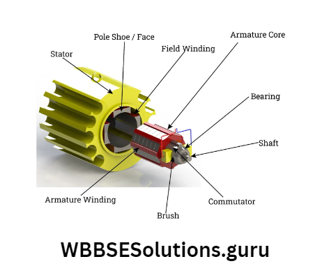
The direction of rotation of the armature coil could be determined with the help of Fleming’s left-hand rule. Due to this fact, the left-hand rule is also called the ‘rule of motor’.

A rectangular coil made of insulated Cu wire, called armature coil, ABCD is placed in between two ponies of a strong magnet NS.

The ends A and D of the coil are connected to a commutator made of Cu which has two split parts R1 and R2.

This combination is mounted on a shaft so that it is capable of rotating around the shaft. A pair of carbon brushes and  B2 press gently against R1 and R2 respectively.

A d. c. source is connected across the carbon brasses B1 and B2. Here note that R1,R2 is connected with the armature coil and B1, B2 with the external circuit.

WBBSE Solutions For Class 10 Physical Science And Environment Chapter 6 current elecrticity increasing the number of truns

Working: When current is passed through the armature coil in the direction DCBA, then according to Fleming’s left-hand rule, the force on the arm AB acts in the inward direction and that force acts on the arm CD in the outward direction.

Force on sides BC and AD are zero as these are directed along the magnetic field. The equal and opposite forces acting on arms AB and CD form a couple.

This couple creates rotational motion in the coil in the anticlockwise direction. While rotating, it, the coil begins to rotate and the arm AB comes out and the arm CD goes in.

When the coil reaches a vertical position, the carbon brushes lose contact with the commutator and momentarily the current gets cut off.

However, due to the inertia of motion, the coil continues rotating in the same direction.

After half rotation, R1 comes in contact with B2 and R2 with B1 At this position the force on the arm CD acts in the outward direction, and on the arm AB it acts in an inward direction.

Due to this, the coil continues rotating in the same direction. The strength of an electric motor can be Increased by

  1. Increasing the number of turns in the armature coil,
  2. Increasing the strength of current through the armature,
  3. Increasing the area of the coil and

Increasing magnetic field strength by inserting a soft iron core inside the armature coil. Because soft iron has the property to get magnetized easily.

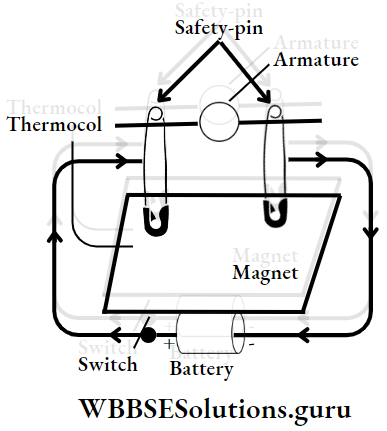
Activity: To make a model of a motor using a battery, magnet, and wires: Wrap a 3-4ft long insulated copper wire around a hollow pipe in 25-30 turns.

Ejecting the pipe, bring out the tightly packed coil. This coil acts as an armature. Strip out the insulation wire from two ends of the coil wire.

Two safety pins are inserted in a thermocol tightly with a gap from one another. Safety pins combined act as a commutator.

Two ends of the coil are brought in to support over two safety pins such that there is free space for rotation of the coil.

Keep a disc magnet into the thermocouple, just below the coil Then, + ve and -ve terminals of an electric cell through a switch are connected with two ends of the safety pins.

When the switch is made ON, current flows through the coil and it starts rotating and as soon as the switch is OFF, the rotation stops. This is a hand-made motor. Can it work with an alternating current? No.

WBBSE Chapter 6 Current Electricity Electromagnetic Induction Concept Of Induced EMF And Induced Current

We knew what happens when a current-carrying wire is placed in a magnetic field. Oersted’s experiment proved that electric current produces a magnetic field.

Can the reverse be also true? Let us see what will happen, as per the activity

Simple Demonstration: Take a coil with which a current-sensitive galvanometer (G) is connected in series having no source and a simple bar magnet (for which the direction of magnetic field lines or magnetic flux is from the N-pole to the S-pole).

Now, move either pole of the magnet (N or S) towards or away from the coil. A deflection in G-needle is seen (either towards the left or right).

But, if the magnet’s motion is stopped, G- the needle does not deflect. Keeping the magnet fixed, when the coil is moved towards or away from the magnet, deflection in G-needle is also seen.

Make the faster motion of either the magnet or the coil, and faster deflection in the G-needle is seen.

WBBSE Solutions For Class 10 Physical Science And Environment Chapter 6 current elecrticity electromagnetic induction 1.

Replacing the magnet with a current-carrying coil, the same type of result is obtained.
Does it happen because of motion?

Actually, when there is a relative motion between a coil and a magnet, the magnetic field lines linking to the cross-section of the coil (i.e. magnetic flux) change (increases/decreases), and because of this change, an emf (potential difference) is induced across two ends of the coil.

When the motion is stopped, no change in magnetic flux takes place, i.e., the existence of emf lasts as long as there is a change in magnetic flux.

The emf produces an electric current called induced current, for which G-needle deflects, and it lasts as long as a change in magnetic flux takes place.

The phenomenon is known as electromagnetic induction. As a whole, mechanical energy (or work) is directly converted into electrical energy.

What a surprising fact Without using a voltage source (d.c.), electric current can be obtained In 1822, Michael Faraday, an English scientist, first time invented it.

Electromagnetic induction is a milestone discovery of Faraday’s laws of electromagnetic induction:

Faraday’s First Law: Whenever there is a change in the magnetic flux linked with a conductor, an e.m.f. is induced in the conductor, as long as there is a change in the magnetic flux.

If the conductor forms a closed coil, an induced current flows through it.

Faraday’s Second Law: The magnitude of induced e.m.f. is directly proportional to the rate of change of magnetic flux linked with the conductor or coil.

Lenz’s law as a consequence of conservation of energy: when the N-pole of the magnet is brought towards the coil, an induced current would flow through the coil such that the magnetic flux would decrease.

This is possible if the induced current would try to oppose the increase of magnetic flux i.e. an N-pole is induced at the face of the coil which opposes the motion of the N-pole of the magnet approaching the coil.

The mechanical energy spent in doing work against such opposing force is transformed into electrical energy, due to which a current flows in an anti-clockwise direction in the coil.

Similarly, when the S-pole of the magnet is brought towards the coil, the induced current flows in a clockwise direction.

Here, in the absence of external force, the K.E. of the moving magnet decreases while the P.E. of the coil increases at the same rate.

Hence, we can conclude that Lenz’s law is based on the law of conservation of energy.

Remember: Lenz’s law is one of the fundamental laws of the universe.

Faraday’s First Law: States the cause of induced EMF or current in a closed coil.

Faraday’s Second Law: States how much emf or current is induced.

Lenz’s Law: States the direction of induced emf or current.

WBBSE Solutions For Class 10 Physical Science And Environment Chapter 6 current elecrticity electromagnetic induction

WBBSE Chapter 6 Current Electricity Direct Current (D.C.) AND Alternating Current (A.C.)

Advantages of a.c. over d.c.: In practical use, generally, 220V a.c. is preferred, but not the d.c. The reason is that the a.c.

voltage can be increased or decreased by the use of a step-up or step-down transformer. It reduces the loss of electrical energy in the transmission lines.

On the other hand, the D.C. voltage can not be increased or decreased and this causes a huge loss of electrical energy in the line wires while passing d.c.

But in machines where big-size motors are used (to run trains,. tram), d.c. is more useful.

WBBSE Chapter 6 Current Electricity Electric Generator

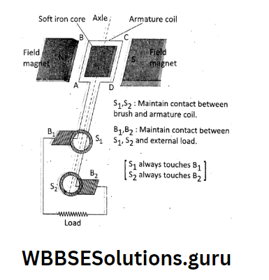
A.C. generator: A.C. generator is a device that converts mechanical energy into electrical energy, working ‘according to the principle of electromagnetic induction.

There are two kinds of generators

  1. A. C. generator and
  2. D. C. generator.

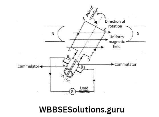
How does it work? : In an A.C. generator, a rectangular coil is rotated in a magnetic field, because of which the magnetic flux changes with time, and an e.m.f.

Is induced between the ends of the coil. The basic construction of the main parts of an A.C. generator is

an armature coil ABCD made of insulated Cu wire wound over a soft iron core,

A field magnet,

Two co-axial slip rings and S1 S2, Two- carbon brushes B1 B2. This arrangement is mounted on an axle.

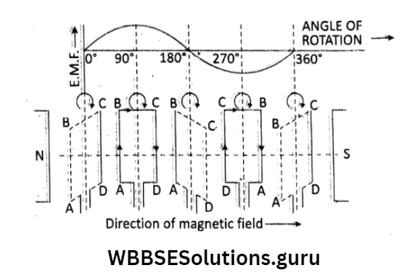
Working: Initially suppose when the armature coil starts rotating, the angle between the direction of magnetic flux lines and the axis of the coil is 0°.

There is no emf induced in the coil, because of no flux change. If the coil is rotated clockwise from 0° to 90°, maximum emf is induced in the coil.

When the coil is further rotated to 180°, the induced emf again becomes zero.

When the coil turns from 180° to 270°, then magnetic flux lines change in the opposite direction, and maximum emf is produced in the opposite direction.

Again when the coil turns to 360°, the rate of flux change again becomes zero, then emf also becomes zero.

During rotation of the coil, the arms AB and CD interchange their positions periodically. Thus the e.m.f. or current changes its polarity as well as magnitude periodically. It is called the alternating e.m.f.

The frequency of a. c. produced in a generator is determined by the number of rotations of the armature coil in one second.

In our country, the frequency of A.C. is 50 Hz. That is, the current changes its direction 100 times in 1 second.

WBBSE Solutions For Class 10 Physical Science And Environment Chapter 6 current elecrticity ac generator

The maximum value of induced e.m.f. in the armature coil of an A. C. dynamo can be increased by

  1. Increasing the area of the cross-section of the coil,
  2. Increasing the number of turns in the coil and
  3. Increasing the speed of rotation of the coil,
  4. Increasing the magnetic field strength.

D.C. generator: Like an a.c. generator, a d. c. generator has a field magnet and an armature coil.

The co-axial slip rings are replaced by two half-cylindrical slip rings which act as a commutator The commutator rotates with the rotation of the armature coil.

In each half-turn, the parts of the commutator pass from one brush to another. Positions of S1; and S2 reverse but the brushes B2 stay in the same position so that the output is always in the same direction.

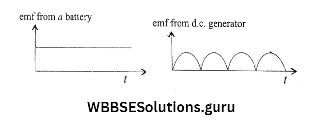
In d.c. the generator also the induced emf is a.c. in nature but this emf is converted into d.c. by using the commutator.

In d.c. generator the current flows in the external circuit only in one direction.

WBBSE Solutions For Class 10 Physical Science And Environment Chapter 6 current elecrticity generation of e.m.f. in the armature coil

The basic principle of thermal and hydroelectric power generation:

Thermal power generation: In a thermal power station, the heat produced by the combustion of fossil fuel (coal) helps to boil water at very high pressure.

When the steam is allowed to rotate the blades of a turbine, the shaft of the turbine rotates at a very high speed. It helps to rotate the armature coil of the a.c. generator and produces thermo-electricity. Here mechanical energy is converted into electrical energy.

WBBSE Solutions For Class 10 Physical Science And Environment Chapter 6 current elecrticity D.C generator

(2) Hydroelectric power generation: Hydroelectricity or hydroelectric power is produced by utilizing the mechanical energy of a high-speed stream of water.

In hilly areas, the water confined in a dam is released to flow through a tunnel at a very high speed, which then falls upon the blades of the turbine, and the turbine rotates.

In the next stage, the a.c. a generator connected to the rotating turbine produces hydroelectricity.

WBBSE Solutions For Class 10 Physical Science And Environment Chapter 6 current elecrticity D.C generator incuded mcf

WBBSE Chapter 6 Current Electricity Domestic Electrical Circuit Components Used In Domestic Electrical Circuit

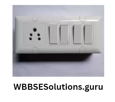
Switch: An electric switch is an on-off device for current in an electric circuit when desired. Commonly used electric switches are lever type (push button type switch).

A switch is always connected to the live wire. In the household circuits, a 5A switch is used for light/fan, and a 10 A / 15 A switch for fridge/washing machine/ geyser.

The main switch is used near the meter board. It has a live wire and a neutral wire. This switch keeps household circuits protected.

Three-pin plug: In a three-pin plug, the top thick pin is for earthing connection, the left-hand pin is for life and the right-hand pin is for neutral connection.

WBBSE Solutions For Class 10 Physical Science And Environment Chapter 6 current elecrticity three pin plug

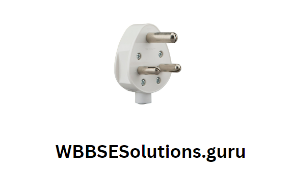
The earth pin is thicker than the other two pins in a three-pin plug: The earth pin is made thicker so that it can be connected first. This ensures the safety of the user.

Moreover, being thicker, the earth pin cannot be inserted into the hole of the socket for a live or neutral connection.

Holes in a socket: The upper bigger hole in the socket is for earth connection, the right-hand hole is for connection to the live wire, and the left-hand hole is for connection to the neutral wire.

WBBSE Solutions For Class 10 Physical Science And Environment Chapter 6 current elecrticity Switch and socket

Live wire, neutral wire: In domestic electrical circuits, there are three wires—Live or phase (220 V), neutral (0V), and earth (0V). The live wire carries the incoming electricity at 220V, so it is very dangerous.

The neutral wire is tied at zero potential. It is taken as a reference potential. The neutral completes the circuit, as it returns electricity to the generator after passing through the appliance.

The earth wire is connected to the earth and is used for precaution of the appliance.

Earthing of electrical appliance: By earthing an electrical appliance such as electric iron, heater, geyser, etc.

it is connected to a low potential. Ultimately by connecting it directly with a local earthing wire.

Local earthing: For local earthing, a thick copper wire kept inside a hollow insulating pipe is buried 2-3m deep in the earth.

It is connected to a thick copper plate of dimensions about 50 cm × 50 cm surrounded by a mixture of charcoal and salt.

WBBSE Solutions For Class 10 Physical Science And Environment Chapter 6 current elecrticity local earthing

If at any stage the iron/heater gets directly connected with the live wire, then the earthing system automatically maintains zero potential and saves from dangerous accidents.

The body/casing of an electrical appliance is always earthed.

If the switch is connected to the neutral wiring electrical appliance remains connected to the live wire and acquires supply voltage, even if the switch is off.

If a person touches the switch, the body comes in contact with the live wire of the appliance. Under such circumstances, the person may get a fatal shock.

To avoid accidents, the switch should always be connected to the live wire.

Color-coding of wires: According to the new international convention, the color coding of wires.

WBBSE Chapter 6 Current Electricity Household Circuits

In household wiring, all the appliances (e.g. bulbs, fans, TV, geyser, etc.) are connected in parallel at the mains, each with a separate switch.

A bulb, and a fan (with regulator) are connected parallel to the distribution box. For each branch line, a separate fuse and switch are connected to the live wire at the distribution box.

Neutral wire and earth wire are common to all branches or appliances.

WBBSE Solutions For Class 10 Physical Science And Environment Chapter 6 current elecrticity households

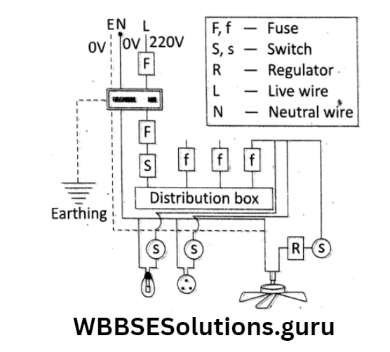
The advantage of the parallel combination is all the appliances get the main voltage and if any one of the appliances goes out of work the electric supply to other appliances does not get affected and they remain functioning properly at the same voltage,

In parallel combination, Req. decreases. So heat loss also decreases.

An electric shock may be caused by an electrical appliance due to poor insulation of the wires.

It is very dangerous to test electrical instruments using domestic power lines.

Activity:  A simple model of an electrical circuit using a battery as a source.

WBBSE Solutions For Class 10 Physical Science And Environment Chapter 6 current elecrticity house holdings

WBBSE Notes For Class 10 Physical Science And Environment

Common Topics

Physics

WBBSE Notes For Class 10 Physical Science And Environment

Chemistry

WBBSE Solutions For Class 10 Physical Science And Environment Chapter 5 Light

WBBSE Chapter 5 Light Reflection Of Light A Spherical Mirror Spherical Surface As A Reflector Of Light

We have learned the nature of the images formed by a plane-reflecting surface such as a plane (flat) mirror.

However, mirrors can be curved also, like steel shining spoons, bowls, dishes, torches, view-finder of cars, street lamps, etc.

These curved surfaces have different shape-spherical, parabolic elliptical, etc. Curved surfaces can form images of different nature than a plane mirror.

WBBSE Solutions For Class 10 Physical Science And Environment Chapter 5 Light concave and convex

Let us take a shining stainless spoon and view our face very close to its curved inner surface. We will see an erect (upright) and enlarged image of our face.

If the spoon is moved away from the face, an inverted diminished image can be seen in the spoon.

WBBSE Notes For Class 10 Physical Science And Environment

Now, if the curved outer surface of the spoon is brought near the face, an erect but diminished image is seen in the spoon.

If the spoon is moved away from the face, the image still remains erect but diminished. Here spoons, bowls, etc. are only approximately spherical surfaces.

in this example, the curved inner surface (i.e., cave side) of the spoon acts as a concave mirror and the curved outer surface (i.e., bulging side) acts as a convex mirror.

Wbbse Class 10 Physical Science Notes

The idea of a Spherical Mirror: These are collectively called spherical mirrors because they are made by cutting from a sphere.

WBBSE Notes For Class 10 Geography And EnvironmentWBBSE Notes For Class 10 History And Environment
WBBSE Solutions For Class 10 Life ScienceWBBSE Class 10 Life Science Multiple Choice Questions
WBBSE Solutions for Class 10 MathsWBBSE Class 10 Maths Multiple Choice Questions
WBBSE Notes For Class 10 Physical Science And Environment


Spherical mirrors are mainly of two types:

  1. Concave mirror and
  2. Convex mirror.

A concave mirror is made by silvering the outer or bulging surface of a hollow sphere such that the reflection of light takes place at the concave, i.e., bent-in-surface.

A convex mirror is made by silvering the inner surface of a hollow sphere such that the reflection of light takes place at the convex, i.e., bulging-out surface.

WBBSE Solutions For Class 10 Physical Science And Environment Chapter 5 Light concave mirrorWBBSE Solutions For Class 10 Physical Science And Environment Chapter 5 Light convex mirror

WBBSE Chapter 5 Light Geometry Of Spherical Mirror

1. Pole The geometric mid-point of the reflecting surface of a spherical mirror is called its pole. P is the pole.

2. Centre of curvature: The geometric center of the hollow sphere of which the spherical mirror is cut, is called its center of curvature. it is denoted by C.

Wbbse Class 10 Physical Science Notes

3. Radius of curvature: The radius of the hollow sphere of which the spherical mirror is cut, is called the radius of curvature of the mirror. length PC (= R) is the radius of curvature.

WBBSE Solutions For Class 10 Physical Science And Environment Chapter 5 Light concave and convex mirrors

In a concave mirror, C is in front of the reflecting surface, and in a convex mirror C is inside the reflecting surface.

4. Principal axis: The straight line joining the center of curvature C and pole P of a spherical mirror is called its principal axis. the line PC represents the principal axis.

5. Aperture: The effective part of the spherical mirror from which the reflection of light occurs is called its aperture. AB is the aperture of the spherical mirror.

Wbbse Class 10 Physical Science Notes

For most of the cases of our present study, we take spherical mirrors with a very small aperture.

WBBSE Solutions For Class 10 Physical Science And Environment Chapter 5 Light

WBBSE Chapter 5 Light Reflection In Spherical Mirror

We got the knowledge of the laws of reflection for plane surfaces in classes VII and VIII. The laws are:

The incident ray, the reflected ray, and the normal lie in the same plane (on the plane of paper at the point of incidence).

The angle of incidence, <i = angle of reflection, <r (Always true).

The same laws of reflection are used for drawing ray diagrams in the case of spherical mirrors to know the position, nature, and size of the image formed by a spherical mirror.

WBBSE Solutions For Class 10 Physical Science And Environment Chapter 5 Light the incident ray

1. Drawing of normal for a spherical mirror: For a curved reflecting surface, the normal always passes through the center of the surface because we know that for an arc, the radius drawn at any point is perpendicular to the tangent drawn at that point.

We can draw the normal at the point of incidence of the spherical mirror by joining point ‘C with the point of incidence

Since for normal incidence <i = 0 and <r = 0, a ray of light passing through or towards the center of curvature gets reflected back along the same path without any deviation in a concave mirror and appears to pass through the center of curvature in a convex mirror.

Wbbse Class 10 Physical Science Notes

2. Drawing of the incident ray and reflected ray: A ray of light incident at any point of a spherical surface is reflected such that at the point of incidence <i = <r.WBBSE Solutions For Class 10 Physical Science And Environment Chapter 5 Light reflection of s light by spherical mirror

A ray of light incident obliquely at P is for a concave mirror and for a convex mirror.

For a ray of light incident parallel to the principal axis of a concave mirror after reflection meets at a point on the principal axis and the same ray after being reflected by a convex mirror diverges or appears to come from a point on the principal axis.

Drawing of many incident rays: For a set of rays incident parallel to the principal axis of a spherical mirror, the ray diagram.

For a set of convergent rays incident on a concave mirror after reflection meets at a point I (in front of a mirror) for which point 0 acts as a virtual object.

Similarly, convergent rays directed towards point O such that PO < PF after reflection by a convex mirror appear to come from the point I. Here I behave as a real image of virtual point object O;

However, divergent rays coming from a point object on the principal axis after being reflected by a concave mirror converge at a point (point image).

Here one point is to be noted that after reflection whether the rays would converge or diverge depends on the position of a point object.

The divergent rays from a point object on the principal axis of a convex mirror, after reflection, diverge more and appear to come from a point inside the mirror.

WBBSE Solutions For Class 10 Physical Science And Environment Chapter 5 Light drawing of many incidents rays

4. Concept of focus and focal length: Principal focus (or focus) is a point on the principal axis at which a beam of light rays parallel to the principal axis, after reflection, actually meets (in the case of a concave mirror) or appears to meet (in case of a convex mirror).

point F refers to the focus of the mirror. A concave mirror F lies in front of the mirror- it is a real point. shows that a convex mirror has a virtual or imaginary focus as it lies behind the mirror.

WBBSE Solutions For Class 10 Physical Science And Environment Chapter 5 Light focus and focal lenght of a concave and conavex mirrors

A concave mirror is called a converging mirror, as all the light rays parallel to the principal axis, after reflection, converge to a point in front of the mirror.

A convex mirror is called a diverging mirror, as all the rays parallel to the principal axis, after reflection, appear to come from a point Situated behind the mirror.

A ray of light passes through F of a concave mirror after reflection becomes parallel to the principal axis, and for a convex mirror a light ray directed towards F after reflection goes parallel to the principal axis according to the reversibility of light.

Focal length: The distance from pole (P) to focus (F) of a spherical mirror is called its focal length. It is denoted as f. Thus, focal length f= PF.

Wbbse Class 10 Physical Science Notes

It is found for a mirror of a very small aperture that point F lies exactly midway between points P and C. That is, focal length \((f)=\frac{\text { radius of curvature }(r)}{2}\)

WBBSE Solutions For Class 10 Physical Science And Environment Chapter 5 Light reflection of an incident ray passes or appears to pass through the foucs

Focal plane: Sets of parallel rays of light after reflection from a concave mirror meet at a point (F’) which always lies in a plane passing through F perpendicular to the principal axis and for a convex mirror sets of parallel rays after reflection diverge.

The divergent rays on being produced backward meet at a common point which lies in a plane passing through F perpendicular to the principal axis.

This plane is called the focal plane. Thus, an imaginary plane passing through the focus and normal to the principal axis of a spherical mirror is called the focal plane of the mirror.

A parallel beam of light rays inclined to the principal axis is focussed at a point in this plane.

WBBSE Solutions For Class 10 Physical Science And Environment Chapter 5 Light focal plane of concave and convex mirror

Activity: Estimation of the focal length of a concave mirror: This can be done with the help of the principle that a parallel beam of light after reflection by a concave mirror meets at a point in the focal plane.

A concave mirror is held facing the window and a plane of white paper (acts as a screen) is kept in front of it.

The position of the mirror is so adjusted to cast a distinct image of the window on the paper.

Measuring the length of the paper from the position of the mirror by a scale, an approximate value of the focal length of the mirror can be obtained.

WBBSE Solutions For Class 10 Physical Science And Environment Chapter 5 Light Image Formed Focal Length Of The Mirror

WBBSE Chapter 5 Light Mechanism Of Image Formation By Ray Diagram

To draw a ray diagram for image formation by a spherical mirror, we are to consider at least any two convenient reflected light rays,

Following the rules:

Rule: 1. A ray of light traveling parallel to the principal axis, after reflection by a concave mirror, passes through its focus (F); and in the case of a convex mirror, the reflected ray appears to be coming from the focus of the mirror.

WBBSE Solutions For Class 10 Physical Science And Environment Chapter 5 Light Reversibility Of Light

For image formation, we need at least two rays and find out either the point of intersection or the point of emergence.

WBBSE Solutions For Class 10 Physical Science And Environment Chapter 5 Light reflection of an incident ray parallel to the principal axis

Rule: 2. A ray of light passing through the principal focus (F) of a concave mirror is reflected parallel to its principal axis; and in the case of a convex mirror, a ray of light traveling towards its principal focus, after reflection, becomes parallel to its principal axis.

WBBSE Solutions For Class 10 Physical Science And Environment Chapter 5 Light ideas of paraxial rays

Rule: 3. A ray of light passing through or towards the center of curvature (C) of a concave and convex mirror respectively, is reflected back along the same path without any deviation.

The idea of Paraxial rays: A beam of light rays, which are parallel and very close to the principal axis, are considered paraxial rays.

WBBSE Solutions For Class 10 Physical Science And Environment Chapter 5 Light Reflection Of Paraxial Rays

For example, rays AB, and DE These rays are taken into account in defining the F of a spherical mirror.

Rays away from the principal axis (GH, KL) are called marginal rays. After reflection, they also converge but do not meet the principal axis at point F.

WBBSE Solutions For Class 10 Physical Science And Environment Chapter 5 Light Realtionship Between F And R For A Concave Mirror

To show r = 2f for paraxial rays: For a concave mirror: P, F, and C are the pole, focus, and center of curvature of a concave mirror.

PC = radius of curvature, r, and PF = focal length,f. Here < BDC = < DCF (alternate angles) and <BDC = < CDF (by < i = < r relation) < DCF = < CDF Hence, <FDC is isosceles.

That is, DF = FC. For a mirror with a very small aperture, D is very close to P. Then DF=FC.

therefore Pf=Fc \(\text { or, } P F=\frac{1}{2} \cdot P C \text { or, } f=\frac{1}{2} r\)

2. For a convex mirror: P, F, and C are the pole, focus, and center of curvature of a convex mirror. PC = radius of curvature, r, and PF = focal length, f.

Here <BDN = <FCD (corresponding angles ; as BD 11 PC, DC the transversal) <BDN = <NDR (by <i = <r relation) and <NDR = <CDF (vertically opposite angles) <FCD = <CDF

Hence, <FDC is isosceles. That is, DF = FC. For a mirror with a very small aperture, D is very close to P. Then DF — PF, therefore, Pf=Fc \(\text { or, } P F=\frac{1}{2} \cdot P C \text { or, } f=\frac{1}{2} r\)

WBBSE Solutions For Class 10 Physical Science And Environment Chapter 5 Light for a convex mirror

Locating the image formed by a concave mirror by drawing a ray diagram: We can study the nature, position, and size of the image formed by a concave mirror for a point object or extended object placed in front of the mirror.

WBBSE Solutions For Class 10 Physical Science And Environment Chapter 5 Light image s

WBBSE Chapter 5 Light Uses Of Spherical Mirrors

Dentists use concave mirrors of a large focal length (f) or a large radius of curvature (r) so that an erect and magnified image of our tooth can be seen inside the dentist’s mirror.

Large/means teeth come within the focal length easily. For the same reason, ENT specialists also use concave mirrors.WBBSE Solutions For Class 10 Physical Science And Environment Chapter 5 Light rear veiw mirror

A concave mirror held near the face always produces an upright and enlarged image between its pole and focus, whereas a plane mirror produces an upright and of the same size image of the face.

Dentist mirror So that the face can be viewed more prominent by a concave mirror. Due to p this fact, a concave mirror is used as a shaving mirror.

Concave mirrors are also used in beauty parlors as make-up mirrors.

WBBSE Solutions For Class 10 Physical Science And Environment Chapter 5 Light Shaving Mirror

A car driver uses a convex mirror as a rearview mirror. A convex mirror diverges the incident light rays and always forms a virtual, erect, and small-in-size image between its pole and focus.

This enables the car driver to see all the traffic approaching from behind. The convex mirror also provides a wider field of view than a plane mirror or a concave mirror. This is the reason why the convex mirror is used as a ‘rear view mirror’.

In the headlight of automobiles, torches, etc. a parabolic metallic mirror is used.

The reason is that the parabolic reflecting surface produces a parallel beam of light for the light rays incident from the bulb which is situated at the focus of the concave surface. This enables car drivers to see objects situated far behind.WBBSE Solutions For Class 10 Physical Science And Environment Chapter 5 Light dentist mirror

WBBSE Chapter 5 Light Refraction Of Light What Happens When Light Travels From One Optical Medium To Another?

In earlier classes, we learned that light travels in a straight line through the same homogeneous medium having the same optical density throughout and its speed doesn’t change.

But when light travels from one homogeneous optical medium to another homogeneous medium, for example, from air to glass, air to water, the path of light bends as soon as it enters into the medium.

That is, the path along which light travels in the second medium is different from the path along which it was passing obliquely in the first medium.

Such a change in direction or bending of light is called refraction of light. It has been found experimentally that there is no change in direction of light when it passes normally.

Definition: The bending of light rays when it is passing obliquely from one transparent homogeneous medium to another transparent medium with different optical densities is called refraction of light.

WBBSE Solutions For Class 10 Physical Science And Environment Chapter 5 Light light Travels In Straight

WBBSE Chapter 5 Light Laws Of Refraction

Refraction Of Light Obeys Two Important Laws These Are:

The incident ray, the refracted ray, and the normal drawn at the point of incidence of two separating media, all lie in the same plane.

For a definite color of light, and for a given pair of media, the ratio of the sine of the angle of incidence, to the sine of the angle of refraction is always a constant.

That is, \(\frac{\sin i}{\sin r}=a \text { constant }(\mu)\) This constant is called the refractive index of the second medium sin (where the light goes after refraction) with respect to the first medium (from where light is incident). This law is also called Snell’s law after the name of the scientist.

Explanation of Snell’s law: We know for the reflection of light at any surface ‘<i = <r’ is always true.

WBBSE Solutions For Class 10 Physical Science And Environment Chapter 5 Light snells law

If we know the value of <i (30° or 40°), we can find the value of <r very easily and vice-versa. Similarly, for refraction of light if </ is given, the value of the angle of refraction <r can be found out using Snell’s law. Snell calculated that

\(\frac{\sin i}{\sin r}=\text { always a constant }=\mu\) example, referring to (ir , r1), (i2, r2), (i3, r3) are different sets of the angle of incidence and angle of refraction. For a given pair of media (here medium 1 and 2) and for a definite color (or wavelength λ).

\(\frac{\sin i_1}{\sin r_1}=\frac{\sin i_2}{\sin r_2}=\frac{\sin i_3}{\sin r_3}={ }_1 \mu_2=\frac{\mu_2}{\mu_1},\) , whatever the values of (i1, r1), (i1, r2), (i3, r3). (Here 1μ2→ r.i of medium 2 w.r.t medium 1)

Hence, from Snell’s law: \(\frac{\sin i}{\sin r}={ }_1 \mu_2=\frac{\mu_2}{\mu_1} \Rightarrow \mu_1 \sin i=\mu_2 \sin r\)

For normal incidence (<i= 0°): The relation p =\(\mu=\frac{\sin i}{\sin r}\)does not hold.

According to Snell’s law:\(\mu \cdot \sin r=\sin 0^{\circ}=0\) As refractive index \(\mu \neq 0\) so that sin r = 0 ⇒ r = 0°. Thus, if i = 0°, then r – 0°, and also the deviation of the ray δ = 0.

Significance of refractive index (r.i. or μ): A medium either optically rarer or denser is measured in terms of its μ of a medium is defined as, \(\mu=\frac{c}{v}=\frac{\text { Speed of light in air or vacuum }}{\text { Speed of light in that medium }} \text {. }\)

It’s a unitless/dimensionless quantity, simply a number, p is a. number that tells us how many times the speed of light is lesser in a medium than in air. For example

1. \(\mu_{\text {glass }}=1.5 \text { means }\) \(1 \cdot 5=\frac{c}{v} \Rightarrow V=\frac{c}{1 \cdot 5}\)

speed of light in glass is 1-5 times lesser than the speed of light in air

2. \(\mu_{\text {water }}\)=1.33 The speed of light in water is 1-33 times lesser than the speed of light in air.

3. \(\mu_{\text {diamond }}=2.42\)means the speed of light in diamond is 2-42 times lesser than the speed of light in air.

Here we see that

(1) larger μ means→ lesser v → optically denser medium and smaller p
mean→ more v → optically rarer medium.

(2) In the relation\(\mu=\frac{c}{v},\). of a medium is compared w.r.t. the r.i. of air. That’s why μ is called the absolute r.i. of the medium.

(3) In relation \(\mu=\frac{c}{v}\) value of c is always greater than v. That’s why μ>1, never μ<1.

(4) As c is constant, so μ depends on v only. reason for the bending of light is the difference in speed of light in different media.

WBBSE Chapter 5 Light Angular Deviation Of Light Ray During Refraction

1. Two cases when light bends: When a ray of light passes from one medium to another, its speed is changed for which refraction of light takes place.

Referring we can say that if the medium doesn’t change then the light would travel in a glass along the dotted line, and due to the medium change light travels in glass through the thick line.

So, when light travels from a rarer medium to a denser medium, it bends towards the normal as i>r.

The deviation of the ray is 5 = (i ~ r). Similarly, while going from a denser medium to a rarer medium, light is bent away from the normal.

Thus, when light travels from a denser medium to a rarer medium it bends away from the normal. the deviation of the ray is, 5 = (r – i), as r > i.

WBBSE Solutions For Class 10 Physical Science And Environment Chapter 5 Light refraction from rarer to deser medium

Two cases when light doesn’t bend: For normal incidence: <i= 0°, and <r = 0°. Here, the speed of light changes, although its direction does not change.

That is light, passes without deviation. If the refractive indices of two media are the same, then a ray of light will pass from one medium to another without any change in the direction of its path.

Because the speed of light will be almost the same in both of the media. For example, a crown glass rod immersed in glycerine can not be seen separately \(\text { (as } \left.\mu_{\text {crown glass }} \approx \mu_{\text {glycerine }}\right)\)

WBBSE Solutions For Class 10 Physical Science And Environment Chapter 5 Light two cases when light doesnt bend

WBBSE Chapter 5 Light Structure Of A Glass Slab And A Prism

Glass slab: In ABCD is a rectangular slab (made of transparent glass or plastic) of the same thickness. It is put in the air.

So, air is a rarer medium, and glass (or plastic) is a denser medium. The slab has two refracting surfaces, AB and CD, of the same thickness.

A ray of light PQ falls on the upper surface (AB) in the air and refracts into the glass along QR.

At the lower surface (CD), the ray QR suffers another refraction at point R and emerges out along RS.

For refraction at point Q: PQ → incident ray, QR → refracted ray, and for refraction at point R: QR incident ray, RS → refracted (emergent) ray.

WBBSE Solutions For Class 10 Physical Science And Environment Chapter 5 Light Prism

Prism: A prism is a piece of transparent homogeneous refracting medium bounded by three rectangular surfaces inclined at an angle and two triangular cross-sections. ABED and ACFD indicate two refracting surfaces, AD the refracting edge, and BCFE the base of the prism.

The two refracting surfaces make an angle (<YXZ) with each other and it is called the refracting angle or prism angle. In the prism the surfaces ABC and DEF are triangular.

The principal section (XYZ) is an imaginary triangle formed by the three refracting surfaces of the prism.

WBBSE Chapter 5 Refraction Through A Glass Slab

A rectangular glass slab PQRS of thickness t. It has two refracting surfaces PQ and RS, parallel to each other.

A ray of light AO falls from the air on the surface PQ at the point of incidence 0 and suffers refraction inside the glass in a straight path along OB.

At point B, on the surface SR, it again suffers refraction and emerges out among BC in the air.

So, refraction takes place at O, from rarer to denser medium, and at B, from denser to rarer medium.

Let at point O, angle of incidence = I, angle of refraction = r, and at point B, angle of incidence = r (v alternate angle), angle of refraction = e (it is the angle of emergence).

WBBSE Solutions For Class 10 Physical Science And Environment Chapter 5 Light angles of refraction

According to Snell’s law, for refraction at point O: 

1. \(\frac{\sin i}{\sin r}=\mu\) (refractive index of glass with respect to air) And, For Refraction at point B:

2. \(\frac{\sin r}{\sin e}=\frac{1}{\mu}\) ( refractive index of air with respect to glass comparing these two, we get, \(\begin{aligned}
& \frac{\sin i}{\sin r}=\frac{\sin e}{\sin r} \Rightarrow \sin i=\sin e \\
& \Rightarrow i=e \Rightarrow \mathrm{AO} \| \mathrm{BC}
\end{aligned}\)

This means that the emergent ray BC is parallel to the incident ray AO i.e., they are in the same direction.

Thus, the light ray suffers no angular deviation, but only lateral displacement occurs. Here, XY is the measure of lateral displacement.

Lateral displacement: In the case of refraction of light through a rectangular glass slab, the perpendicular distance drawn between the emergent ray and the incident ray is called lateral displacement.

Refraction through a prism: Let ABC is the principal section of a prism with prism angle <BAC = A. On refracting face AB of the prism, in rarer medium OP is the incident ray and PQ is the refracted ray in the denser medium.

The angle of incidence is i1 and the angle of refraction is r1; and on refracting face AC of the prism, the respective angles are r2 and i2.

<p Thus, QR is the emergent ray and i2 is the angle of emergence, <LMQ is the measure of the angle through which the emergent ray deviated from the incident ray and is called the angle of deviation. It has a value of δ = i1 + i2 – A.

WBBSE Solutions For Class 10 Physical Science And Environment Chapter 5 Light deviation by a prism

Derivation of δ using Simple Geometry: From ΔPMQ, external <LMQ = <MPQ+<MQP………(1)
Since < MPQ-Angle deviation at point p= (i1 – r2) and
<MQP = angular deviation at point Q=(i1 -r2) .

Thus, δ = (i1,-r1) + (i2-r2) = i1 + i2  – (r1+r2)………… (2)

Also for the quadrilateral APNQ, <A + <APN + <N+<AQN=360° ⇒ <A+90° +<N+ 90° =360° Thus, A+<N=180°……….(3),

Again For the  Δ PNQ: ( r1+r2)+<N=180°…………….(4)

Comparing Equations (3) and (4): A= r1+ r2 …………(5)

Hence from Equations (2) and (5): δ= i1+ i2 -A………..(6)

i-δ graph: i-δ graph for the refraction of light through a prism The i-δ graph explains that as the angle of incidence

1. increases, the angle of deviation (δ) first decreases and reaches a minimum value for a particular value of i. By further increasing I, the value of δ also increases. This minimum value of δ is δmin.

It can be proved that the angle of deviation becomes minimum (δmin) under the condition: i1= i2 i.e., angle of Incidence = angle of emergence; And also r1 = r2.

WBBSE Solutions For Class 10 Physical Science And Environment Chapter 5 Light i graph

The position of the prism with respect to the incident ray, at which the incident ray suffers minimum deviation is called the position of minimum deviation of the prism. At this position, i2 = i2 and also r1 = r2.

WBBSE Chapter 5 Light Structure Of Spherical Lenses

A lens is a piece of transparent refracting medium (like glass, quartz, or transparent plastic) bounded by two spherical or one spherical and one plane surface.

We see various uses of lenses in cameras, spectacles, microscopes, telescopes, and in other optical instruments.

Out of two boundary surfaces, one must be spherical. For most of the lenses, we see both surfaces are spherical.

Types of lenses: Lenses are broadly classified into two types:

  1. Convex or converging lens, and
  2. Concave or diverging lens.

A convex lens is thick in the middle and thin at the edges. It converges parallel rays of light incident on it.  A concave lens is thick at the edges and thin in the middle. It diverges parallel rays incident on it.

Further classification of lenses: Different types of convex lenses:

  1. A convex lens is of three types, such as
  2. bi-convex or equi-convex lens,
  3. plano-convex lens and
  4. concavo-convex lens. shows their shapes of them. Here first part (bi, piano, concave Indicates ‘shape’ &, last part (convex) indicates the ‘nature’ of the lens.

An equal-convex lens has both of its surfaces convex; a plano-convex lens has one surface plane and the other surface convex; and a concavo-convex lens has one surface convex and the other surface concave.

For all types, the lens is thicker in the middle and thinner at the edges. The net nature of all three lenses is like a convex lens i.e. converging light rays;

Different types of concave lenses:

  1. A concave lens is of three types, such as
  2. equi-concave lens,
  3. Plano concave lens, and
  4. convexo-concave lens.

The shapes An equi concave lens has both its surfaces concave; a plano concave lens has one surface plane and the other surface concave; and a convexo-concave lens has one surface concave and the other surface convex.

WBBSE Solutions For Class 10 Physical Science And Environment Chapter 5 Light Convex Lenses

For all types, the lens is thinner in the middle and thicker at the edges.  The net nature of all three lenses is like a Concave lens i.e. they diverge light rays.

WBBSE Solutions For Class 10 Physical Science And Environment Chapter 5 Light Concave Lenses

Terms related to a lens:

Centre of curvature: Each surface of a lens is part of a sphere. The centers of two spheres are called the centers of curvature of those surfaces of the lens.

C1 and C2 are the centers of curvature of surfaces 1 and 2 respectively.

Principal axis: The line joining the two centers of curvature of two spherical surfaces of a lens is called its curved principal axis. In C1C2 is the principal axis.

For a lens having one plane surface, the position of the center of curvature is at infinity.

The radius of curvature: The radius of the sphere of which the lens is a part is called the
radius of curvature of the lens.

For an equi-convex or equi-concave lens, the radii of curvature of two surfaces are equal.  If the thickness of a lens radius of curvature is, it is considered a thin lens.

WBBSE Chapter 5 Light Refraction Through A Lens

The optical center of a lens: For a thin lens, the thickness is so small that it is negligible. But for a thick lens, thickness is to be taken into account.

For a thick lens, the ray incident on the lens and the emergent ray from the lens does not lie on the same line.

So, there occurs lateral displacement of the emergent ray Actually light deviates from its own path. The optical center for a thick lens is a fixed point on the principal axis.

An oblique ray of light incident at one curved surface of the lens emerges parallel to the incident ray.

The path of the ray within the lens intersects the principal axis at a fixed point, called the optical center. It is equidistant from the two curved surfaces of the lens.

PQ →incident ray and RS →the refracted ray. They are parallel to each other. The passage of the ray through the lens (here QR) touches the principal axis at O. Here, O is the optical center.

WBBSE Solutions For Class 10 Physical Science And Environment Chapter 5 Light optical centre of a lens

The optical center of a thin lens: It is a point on the principal axis of a thin lens through which a ray of light passes undeviated and undisplaced. The role of the optical center is similar like

the pole of a spherical mirror illustrates the optical center (O) for both convex and concave lenses.

Converging action of a convex lens: A convex lens may be considered a combination
of a number of prisms such that the prisms in the upper and lower halves have their bases downward towards the principal axis, while the central portion of the lens is just like a glass slab.

We know that the rays of light on passing through a prism, tend to deviate towards its base.

The light ray incident parallel to the principal axis after refraction by a small prism deviates towards the base of the prism, whereas the rays passing through the central portion deviate through lesser angles.

Thus, all the rays after refraction converge or meet at one point (called the focus points). This explains the converging action of a convex lens.

WBBSE Solutions For Class 10 Physical Science And Environment Chapter 5 Light centre of curvature, principal axis

Diverging action of a concave lens: A concave lens may be considered as a combination of a number of prisms such that the prisms in the upper and lower halves have their bases towards the edges.

As we know that the rays of light passing through a prism, tend to deviate toward its base.

The ray incident parallel to the principal axis after refraction by a small prism deviates maximum towards the base of the prism whereas the light ray passing through the central portion deviates through lesser angles.

Thus, all the rays after refraction diverge or appear to come from a point (called the focus point). This explains the diverging action of a concave lens. Focus, focal plane, and focal length.

WBBSE Solutions For Class 10 Physical Science And Environment Chapter 5 Light thick lens

WBBSE Chapter 5 Light Focus Focal Plane And Focal Length

A spherical mirror has one principal focus, but a lens has two principal foci. Because a spherical mirror has only one spherical reflecting surface, whereas a lens has two refracting surfaces.

The two principal foci of a lens (F1 and F2) are equidistant from the optical center, (focal length). In

In such that OF1 = OF2 = f our syllabus, we will study only thin lines which are sometimes represented by a straight line. First focus (not so much important in the discussion of the lens)

WBBSE Solutions For Class 10 Physical Science And Environment Chapter 5 Light converging action of a convex lens

Definition: First focus (F1) of a convex lens is a point on the principal axis such that the rays of light coming from this point after refraction become parallel to the principal axis. If an object is kept at an F2 then the image is formed at infinity.WBBSE Solutions For Class 10 Physical Science And Environment Chapter 5 Light diverging action of a concave lens

The first principal focus (F1) of a concave lens is a point on the principal axis such that the rays of light coming towards this point after refraction becomes parallel to the principal axis.

(F2) Second focus or Principal focus ‘focus’ means ‘second focus’ is lens discussion and is important)

Definition: Rays of light coming parallel to the principal axis of a convex lens after refraction become convergent to a common point (F2) on the principal axis. This common point is called the principal focus of the convex lens.

WBBSE Solutions For Class 10 Physical Science And Environment Chapter 5 Light second focus or principal focus

Rays of light coming parallel to the principal axis of a concave lens after refraction diverge.

The divergent rays being produced backward appear to come from a common point (F2) on the principal axis. This common point is called the principal focus of the concave lens.

Focal length: The distance of the principal focus of a lens from its optical center is called its focal length. OF2 = f is the focal length.

Focal plane:  (a), parallel rays of light incident on a convex lens after refraction converges to common points such common points lie on a plane perpendicular to the principal axis.

For a concave lens, parallel light rays diverge from common points which also lie on a plane perpendicular to the principal axis.

This plane is called the focal plane. For a lens, the position of the focal plane is fixed.

Definition: A plane passing through the focus and normal to the principal axis of a lens is called the focal plane.

  1. The focal length of a lens depends on the
  2. The refractive index of the material of the lens,
  3. The radii of curvature of two spherical surfaces, and
  4. The color of light.

If the refractive index of the surrounding medium is more than that of the lens medium, then a convex lens behaves like a concave lens, and a concave lens behaves like a convex lens.

For example, an air bubble in water behaves like a concave lens (refractive index: μwater air ).

WBBSE Solutions For Class 10 Physical Science And Environment Chapter 5 Light a spherical mirror

WBBSE Chapter 5 Light Image Formation By A Thin Lens Using Ray Diagrams

To draw the ray diagrams of image formation by a convex or concave lens, we are to choose any two rays out of the three rays Here O is the optical center and F1 and F2 respectively are the first and second principal focus of the lens.

Generally, when we say focus, we mean F2 i.e., second principal focus. Both F1 and F2 are at the same distance from O, i.e., OF1 = OF2 = f (focal length of the lens).

WBBSE Solutions For Class 10 Physical Science And Environment Chapter 5 Light three Construction rays

Rules for drawing ray diagrams: –

A ray of light through the optical center of a convex or concave lens passes un-deviated

A ray of light incident parallel to the principal axis of a convex lens after refraction passes through the second principal focus (F2), and for a concave lens, the ray appears to come from the second principal focus (F2)

A ray of light passing through or directed towards the first principal focus (F2) after refraction passes through the principal axis In the following ray diagrams: AB → extended object kept normal to the principal axis; AB→ image formed. F1 → first focus, F2→ second or principal focus.

Formation of real, inverted, diminished image:
The object is kept beyond 2F1 (in between infinity & 2F1 ). Image is formed between F2 and 2F2. The image is real and inverted and diminished.

WBBSE Solutions For Class 10 Physical Science And Environment Chapter 5 Light image foramtion by a convex lens for the objec beyond 2F1

Formation of real, inverted, magnified image:
An object is kept between 2F2 and F1 Image is formed beyond 2F2. The image is real & inverted and magnified.

WBBSE Solutions For Class 10 Physical Science And Environment Chapter 5 Light image formation by a convex lens for the object between F1 And 2F1

Formation of virtual, erect, and magnified images: The object is kept between F1 and O. The image is formed on the same side as that of the object.

The image is virtual, erect (upright), and magnified. This case is unique because it is the only case in which a convex lens produces a virtual image.

WBBSE Solutions For Class 10 Physical Science And Environment Chapter 5 Light image formation by a convex lens 3

Geometric construction of images in the concave lens:

Generally, a concave lens always forms a diminished image (for objects kept at any point except infinity). Because it diverges all the light rays incident on it.

The rays after refraction do not intersect but they appear to come from the points between A’ and B’ as The image is formed on the same side of an object between O and F2.

It is virtual and upright and diminished.

WBBSE Solutions For Class 10 Physical Science And Environment Chapter 5 Light image formation by a concave lens

Linear magnification of image: Flow many times the height of the image is greater or smaller than the height of an object is expressed in terms of magnification. It is expressed as the ratio of image height to object height.

Thus, linear magnification (m) = \(\begin{aligned}
& =\frac{\text { Image height }(I)}{\text { Object height }(\mathrm{O})} \\
& =\frac{\text { Image distance }(v)}{\text { Object distance }(u)}
\end{aligned}\)

If m > 1, then image height > object height (magnified image).
If m < 1, then image height < object height (diminished image).
If m is positive, then an erect image can be obtained. And if m is negative, then an inverted image can be obtained.
Linear magnification is a unitless quantity.

WBBSE Chapter 5 Light A Simple Camera And Human Eye As The Application Of Image Formation By A Lens

The basic structure of a simple camera: The working of a simple camera is based on the principle that if an object is placed at a distance more than twice the focal length of a convex lens, then a real, inverted, diminished image is formed at a distance less than twice of the focal length on the other side.

WBBSE Solutions For Class 10 Physical Science And Environment Chapter 5 Light simple camera

The diagram of a simple camera. It uses a film on which a picture (photo) is taken.

When the camera is clicked, the shutter opens for a short duration of time and allows the entry of light that duration to form a real, inverted, and diminished image on the photographic film.

Photographs of near and distant objects can be taken by the same camera by adjusting the distance of the camera lens from the photographic film with the focusing ring.

Human eye: The human eye is like a simple camera having a bi-convex lens on one side and a photo-sensitive screen called the retina on the other side.

When we look at something our eye lens focuses the object on our retina so that we can see the object.

In the human eye, the crystalline lens along with the cornea, aqueous humor, and vitreous humor Human eye forms a converging system, which forms a real, inverted, and diminished image on the retina.

WBBSE Solutions For Class 10 Physical Science And Environment Chapter 5 Light human eye

The image formed by a camera is permanent while that formed by the eye on the retina is not permanent.

Ciliary muscles help to change the size of the crystalline lens in the human eye and thereby its focal length such that the focal length of the lens automatically changes to obtain an image always on the retina. Sclerotic is the outermost covering of the human eye from the inside.

It protects the internal parts of the eye. The cornea is the outermost covering of the human eye from the outside.

Choroid darkens the eye from the inside and protects the eye from internal reflections if any. The pupil appears black because no light is reflected from the pupil.

Normal eye: The human eye in normal condition is capable of focussing light rays coming from nearby objects and also far away objects.

Such an ability of the eye lens is called the power of accommodation. How far can a normal eye see clearly without strain? A person with a normal eye can see nearby objects like a book.

For a normal eye, the closest distance is about 25 cm from the eye. Now, if the book is brought at a distance less than 25 cm from the eye, it cannot be seen clearly without strain.

The minimum distance at which a normal eye is able to see objects clearly without strain is called the near point of the eye.

A person with having normal eye can clearly see very far-off things like clouds or mountains.

The farthest point up to which the normal eye is able to see objects clearly without strain is called the far point of the eye. For a normal eye, the far point is at infinity.

The distance between a near point and the far point of the eye is called the nearby objects and distant objects appear clear.

WBBSE Solutions For Class 10 Physical Science And Environment Chapter 5 Light Normal Eye And Distant Objects Appear Clear

Defects of the human eye: Sometimes, the eye lens may lose its power of accommodation,

Such that the focus: and length of the eye lens cannot be adjusted as required for the formation of sharp images or the retina. This is called the defect of vision.

The major two types of defects of the human eye are myopia or short-sightedness or near-sightedness and hypermetropia or long-sightedness or far-sightedness.

Short-sightedness or myopia: A person who has myopia can see nearby objects clearly but cannot see distant objects distinctly.

The defect arises due to high converging power eye ens. shorter/compared to the normal eye and longer (enlarged) eye-ball so that in a myopic eye, the image of the distant object is not formed at the retina, but rather formed at a point in front of the retina.

This defect is usually seen in youths. That’s why, distant objects will appear blurry. So to see distant objects myopic eye needs spectacles.

Long-sightedness or hypermetropia: A person who has hypermetropia can see distant objects clearly but cannot see nearby objects distinctly.

That is, for the hypermetropic eye, the nearby objects like letters of books appear blurry whereas the writings on a distant board appear clear.

The defect arises due to the low converging power of the eye lens longer/compared to the normal eye and shorter eyeball so that the near point of the hypermetropic eye is more than 25 cm. Of course, defective near point for different people is different.

In a hypermetropic eye, the image of the nearby object is not formed on the ret but rather at a point slightly behind the retina.

So to see nearby objects clearly the persons need spectacles. The defect is mostly seen in old persons.

The defect of hypermetropia is corrected by using a convex lens of suitable focal The convex lens converges the light rays more to make them on the retina.

The convex lens should be of suitable power so that the lens can produce a virtual image of the nearby object on the near point of the hypermetropic eye.

WBBSE Solutions For Class 10 Physical Science And Environment Chapter 5 Light Hypermetropic and correction for hypermertropic eye

Now the person can see a clear image of the object. A student is unable to read the blackboard while sitting in the last row the defect is myopia.

The student has to use spectacles with positive power. A man suffering from hypermetropia uses spectacles with negative power.

A man may suffer from both myopia and hypermetropia. and he requires spectacles with bifocal lenses, the upper part of which is a concave lens to see distant objects and the lower part of it is a convex lens to see nearby objects distinctly.

Activity: Making a model of a camera.

Apparatus and materials: Hard interlocking rectangular boxes with one side open. These are designed such that they can fit with each other.

A magnifying glass is taken as a focusing lens. A piece of translucent plastic/paper or the tracing paper is taken on which the image can be focussed using the lens. Cellotape, gum, black cloth or paper, etc.

Different parts of a simple camera are Cut a hole in the front box. The hole would be equal to the diameter of the magnifying glass. Fix up the magnifying glass into the hole with sellotape.

The translucent paper is fitted at the back of the box with tape. The boxes are arranged such that the magnifying glass can be moved back and forth (the focussing mechanism of the simple camera).

A black cloth/paper is put over the camera to prevent external light to fall on the tracing paper.

WBBSE Solutions For Class 10 Physical Science And Environment Chapter 5 Light making a model of a camera

With bifocal lenses, the upper part of which is a concave lens to see distant objects and the lower part of it is a convex lens to see nearby objects distinctly.

Point the camera towards the window. Moving the mobile part forward and backward focussing is done and one can see an upside-down image on the tracing paper. To take a photo, a film is to be placed at the end of the camera.

WBBSE Chapter 5 Dispersion Of Light What Happens When White Light Passes Through A Prism?

Dispersion of light What happens when white light passes through a prism?
Dispersion of white light: Sir Isaac Newton first observed that when a narrow beam of white light is passed obliquely through a glass prism, the light is split up into seven different colors.

A colored patch is seen on a white screen placed on another side of the prism, which is called the spectrum The colors in the spectrum are arranged in a particular order.

From the top: Red, Orange, Yellow, Green, Blue, Indigo, and Violet. The sequence of colors  Dispersion by a prism is VIBGYOR (taking the initial letters of each color).

One beautiful natural example of the dispersion of light is the rainbow where white sunlight is seen to be split into different colors.

Definition: The splitting of white light into its seven constituent colors while passing through a refracting medium (like a prism) is known as the dispersion of light.

The band of colors (VIBGYOR) obtained by the dispersion of light is called a spectrum.

Reason: Why a simple glass prism splits white light into different colors?
When light from the air enters into the glass, there happens bending of its path and once again when the light comes out from glass to air, bending of the path takes place.

As a whole, while passing through a prism, light is refracted toward the base of the prism. We learned that white light is made up of seven different colors. Also, different colors of light have the same speed in air (3 x 10⁸ m/s).

But the moment, white light strikes the glass prism, the speed of different colors becomes different in the glass prism.

Red color has maximum speed and violet color has minimum speed. Because of the change in speed of different colors, they bend at different – angles in the glass prism.

The red light bends the least and the violet light bends the most. The speed of light is different for the light of different colors in a medium other than air or vacuum.

Wavelength (λ) means the length of one full wave. The speed of light increases with an increase in the wavelength of light.

For example, in visible light because violet red, as \(v_{\text {violet }}<v_{\text {red }} \text {, as } \mu=\frac{c}{v} \text {. So we get } \lambda_{\text {violet }}<\lambda_{\text {red }}\)So we get According to Snell’s law, different colors have different refractive indices in a glass prism.

Thus, for the same angle of incidence of white light, there are different angles of refraction and hence the angular deviation is different for different colors.

A beam of light is split up into seven colors when refracted through a glass prism, but not by a rectangular block of the same glass.

While passing through a rectangular glass block, the incident light and the emergent light become parallel to each other. So, there is no question of splitting.

WBBSE Solutions For Class 10 Physical Science And Environment Chapter 5 Light Dispersion by a prism

WBBSE Chapter 5 Light Idea Of Monochromatic and Polychromatic Light

In Greek, ‘mono’ means ‘one’ and ‘poly’ means ‘many’, and ‘chroma’ means ‘color’. Monochromatic light is light made of one (single) color, i.e., of a single wavelength.

Polychromatic light exhibits several (more than one) colors and contains more than one wavelength.

For example, each color of the rainbow is monochromatic in nature, but white light formed by mixing the seven colors of the rainbow is polychromatic in nature.

What is the role of the color of light on the appearance of the color of an object?
A white beam of light falling on a colored opaque object absorbs all the colors of white light except the one of its own color and reflects light of that particular color only.

For example—

A white beam of light incident on a red flower reflects only the red color of white light and absorbs all other colors. So that the flower appears red.

A white beam of light White color is not actually white—it consists of all seven colors (VIBGYOR).
Different colors of light have different wavelengths.

Black is not a color—when all colors of light are absorbed by an object, it looks black.
incident on a green leaf reflects only the green color of white light and absorbs all other colors. So that the leaf looks green.

A green appears black in red light. The leaf can reflect only the green color of white light and can absorb the red light so that no color is emerge out of the leaf illuminated by red light.

A blue glass appears blue as it. transmits only the blue color of white light and practically absorbs of all other colors.

If we look at the sun through one red glass and one blue glass keeping in contact with each other, the glass combination appears black.

The red glass only allows the red color of sunlight and absorbs other colors. The blue glass kept in contact with red glass absorbs the red color. So, no color emerges out of the glass combination.

WBBSE Chapter 5 Light Wave What Kind Of Wave Is Light Wave?

Light is a form of energy. It is a wave. The phenomena of interference and diffraction of light prove the fact that light travels in a vacuum or air in the form of a wave.

Do you know that ordinary light is a transverse electromagnetic wave? Because light is associated with the vibrations of an electric field \((\vec{E})\) and magnetic field \((\vec{B})\) mutually perpendicular to the direction of its propagation.

The speed of light is maximum in a vacuum and is equal to (this value is considered a fundamental constant in the study of science). \(c=3 \times 10^8 \mathrm{~ms}^{-1}\)

Speed (c), frequency (f), and wavelength (λ) of electromagnetic waves are related as c=fλ (i)

Wavelength (measures the length of an individual wave and frequency (f) describes how many waves per second a wavelength produces.

The refractive index in terms of velocity: According to the wave theory of light, the absolute refractive index (μ) of a transparent medium can be expressed as the ratio of the speed of light in a vacuum to the speed of light in the medium

Thus, \(\mu=\frac{\text { Speed of light in vacuum (c) }}{\text { Speed of light in medium (v) }}\)

In general, the relative refractive index of medium 2 with respect to 1 medium (i2) can be expressed as:

\({ }_1 \mu_2=\frac{\mu_2}{\mu_1}=\frac{\text { Speed of light in medium } 1}{\text { Speed of light in medium } 2}=\frac{v_1}{v_2}\)

These relations show that the amount by which a ray of light refracted depends on how much its speed changes.

The greater the change in speed, the greater the refractive index of the medium. O If 1 and 2 correspond to rarer and denser media, then,\(\mu_2>\mu_1 \Rightarrow{ }_1 \mu_2>1\)
v1>v2 So, when a ray of light passes from a rarer to a denser medium, the speed of light decreases.\(\mu_2>\mu_1 \Rightarrow{ }_1 \mu_2>1,\)

then \(\text { If }{ }_1 \mu_2<1 \Rightarrow \mu_2>\mu_1\) so when light passes from a denser to a rarer medium, the speed of light increases. if v1=v2 then, etc. So light enters into the second medium without any change in speed.

WBBSE Solutions For Class 10 Physical Science And Environment Chapter 5 Light electromagnetic waves

The refractive index in terms of wavelength: At the time of refraction, when light enters from medium 1 into medium 2, its frequency remains unchanged but speed and wavelength both are changed.

Suppose light causes sunburns μ12=1 Next comes X-rays which pass through soft tissues but not through bones or denser materials, y-rays produce even shorter X, higher /and more energy.

Its length is smaller than the size of an atomic nucleus.] lie f medium 1 and 2 respectively.

If X and X denote the wavelength and or the frequency of light of definite color, in a vacuum, and in any other transparent medium, then we can write,  λ0 and λ denote the wavelength and f the frequency of light of definite color, in a vacuum and in any other transparent medium, then we can write,

\(\text { Refractive index; } \left.\mu=\frac{\mu_2}{\mu_1}=\frac{c}{v}=\frac{f \lambda_0}{f \lambda}=\frac{\lambda_0{ }^*}{\lambda} \text { As } c=f \lambda_0 \text {, and } v=f \lambda\right]\)

That is The refractive index is inversely proportional to the wavelength of light. since

\(\lambda_{\text {red }}>\lambda_{\text {violet }} \text { so } \mu_{\text {violet }}>\mu_{\text {red }}\)

Electromagnetic waves and Electromagnetic spectrum: Do you believe that we are always surrounded by different kinds of electromagnetic waves such as waves transmitted by radio, TV stations, waves emitted from Wi-Fi equipment, computers, phones, microwave ovens, visible light from the sun, and other stars?

Scientists described electromagnetic waves on the basis of their wavelengths (λ) or frequency (f), and the pattern is called the electromagnetic spectrum At one end of this pattern lies radio waves and y-rays at the other end.

Radio waves have the longest  (nearly the length of a football ground or more) and the lowest / in the spectrum.

After radio waves lie microwaves which have shorter X and higher f—microwave ovens, phones, and readers use them. Next comes IR light.

We cannot see this part. We feel it as heat. Visible light occupies a narrow slice in the spectrum lying between IR light and UV light.

\(\lambda_{\text {red }} \rightarrow \text { largest, } \lambda_{\text {violet }} \rightarrow \text { lowest. }\)As we move from red light to violet light, X decreases and/or increases. Next comes UV light.

Skin produces vitamin D when exposed to UV light, but excessive Uv Light causes sunburns.

Next UV light causes sunburns. Next comes X-rays—which pass through soft tissues but not through bones or denser materials, γ-rays produce even shorter λ, higher and more energy. Its length is smaller than the size of an atomic nucleus

WBBSE Solutions For Class 10 Physical Science And Environment Chapter 5 Light wave lenght

WBBSE Chapter 5 Light Scattering Of Light

Scattering of light is a phenomenon of change in the direction of propagation of light waves caused by striking different atmospheric particles like dust particles, huge no of air molecules (mainly N2 and O2 molecules), and so on, of size smaller than the wavelength of visible light.

Sunlight consists of seven different colors of light having different wavelengths. When sunlight enters the atmosphere, the air molecules (size < 0.4 nm) scatter different colors differently. Scientist Rayleigh was the first to explain the scattering of light.

Rayleigh established mathematically that the intensity of scattered light is inversely proportional to the fourth power of the wavelength of the incident light Scatterme Thus, shorter wavelengths are more scattered than longer wavelengths.

Blue color has the smallest A, so the blue color is scattered the most, and red has the largest A, which is scattered the least.

So, whenever we look up at the sky, we see blue color. This is the fact why the sky appears blue.

If the earth had no atmosphere, there would be no question of scattering of light. The sky would then appear dark (as an astronaut sees the sky from outer space).

WBBSE Solutions For Class 10 Physical Science And Environment Chapter 4 Thermal Phenomena

WBBSE Chapter 4 Thermal Phenomena Thermal Expansion Expansion of solids from everyday experience

A tightly fitted metal cap on a bottle can be loosened by heating the neck of the bottle. On heating, the metal cap expands and it gets space to be loosened.

While laying railway tracks, if the rails are placed end to end, they may bend due to expansion in summer and it may cause accidents.

To avoid it, small gaps are left between two successive rails to allow them to expand for expansion

Wbbse Class 10 Physical Science Notes

WBBSE Solutions For Class 10 Physical Science And Environment Chapter 4 Thermal Phenomena gaps are in a railway track Electric wires are kept sagging

Telephone wires and electric wires are always kept sagging to prevent their snapping when they contract in winter Almost all substances, whether solid, liquid, or gas, expand on heating

There are a few exceptions to the rule: water from 0°C to 4°C, and silver iodide from 20°C to 141°C.

And contract on cooling Such expansion of any substance on heating is known as thermal expansion.

WBBSE Notes For Class 10 Physical Science And Environment

A solid has a definite shape. So when a solid is heated, it expands in all directions, without any change in its mass. That is, on heating, the length, surface area, and volume of a solid all increase. Thus there are three kinds of thermal expansion in the case of solids:

  1. Linear Expansion,
  2. Superficial or surface Expansion and
  3. Cubical or volume Expansion.

On heating, the increase in the length of a solid is called linear expansion, the increase in surface area is called surface expansion, and the increase in volume is called volume expansion.

The liquids and gases do not have a definite length, area, or shape, but they have a definite volume. So, liquids and gases have only volume expansion.

Wbbse Class 10 Physical Science Notes

As the molecules in solids are very tightly packed, so thermal expansion of solids is very small.

Apparently, it is difficult to understand such a small thermal expansion. Through experiments, it can be proved.

WBBSE Notes For Class 10 Geography And EnvironmentWBBSE Notes For Class 10 History And Environment
WBBSE Solutions For Class 10 Life ScienceWBBSE Class 10 Life Science Multiple Choice Questions
WBBSE Solutions for Class 10 MathsWBBSE Class 10 Maths Multiple Choice Questions
WBBSE Notes For Class 10 Physical Science And Environment


Bar and gauge experiment: Let us take a bar and a gauge set-up which consists of a metal bar and a metal gauge.

When both of these two are at room temperature, the bar just fits into the gap in the gauge. But when the bar is heated using a burner, it does not fit into the gap in the gauge.

This happens because the bar expands on heating and becomes longer in size than the gap in the gauge.

WBBSE Solutions For Class 10 Physical Science And Environment Chapter 4 Thermal Phenomena bar and gauge set-up showing thermal expansion of soild

If the bar is then allowed to cool down to room temperature, after some time it is seen that the bar again fits into the gap in the gauge. This happens because the bar contracts on .pooling.

Thus, the bar and gauge set-up proves the thermal expansion of solid by heating and contraction by cooling.

Bimetallic strip experiment: Let us take a bimetallic strip, made up of two strips of different materials, such as brass and iron, having the same dimensions placed one over another lengthwise and properly riveted at their ends.

At room temperature, the bimetallic strip is straight. Using a burner, when the bimetallic strip is heated the strip bends with the brass portion on the outer side.

Wbbse Class 10 Physical Science Notes

The experiment proves that brass expands more than iron for the same rise in temperature. If the strip is cooled (even below room temperature) brass contracts more than iron.

Bimetallic strips are used in electrical heating devices like electric irons, geysers, ovens, refrigerators, toasters, etc.

where power gets cut off automatically as soon as the temperature reaches a desired value.

WBBSE Solutions For Class 10 Physical Science And Environment Chapter 4 Thermal Phenomena Bismetallic Strip Experiment

On heating, the increase in the length of a solid is called linear expansion, the increase in surface area is called surface expansion, and the increase in volume is called volume expansion.

The liquids and gases do not have a definite length, area, or shape, but they have a definite volume. So, liquids and gases have only volume expansion.

Let us take a thin rod of length at the initial temperature On heating the rod through let the final length become So, the increase in length = \(\left(I_2-I_1\right)\) for the increase in temperature

=\(\left(t_2-t_1\right)\) By experiments, it is found that the increase in length of a rod is—

1. Directly proportional to its original length, if the increase, at tx in temperature is not very large.

That is  \(\left(I_2-I_1\right) \propto I_1 \ldots\) And

2. Directly proportional to its original length, if the increase in temperature, is not very large. that is

⇒ \(\left(I_2-I_1\right)\)\(\propto\left(t_2-t_1\right)\)

[where α is a constant of proportionality and it is called the Si ‘coefficient of surface expansion’]

Combining (1) And (2)

⇒ \(\left(I_2-I_1\right) \propto I_1\left(t_2-t_1\right)\)

or \(\left(I_2-I_1\right)=I_1 \cdot \alpha \cdot\left(t_2-t_1\right)\)

or, \(\alpha=\frac{I_2-I_1}{I_1\left(t_2-t_1\right)}\)

i.e., Coefficient of linear expansion=\(\frac{\text { Increase in length }}{\text { Original length } \times \text { Rise in temperature }}\)

⇒ \(\text { If } I_1=1 \text { and } t_2-t_1=1 \text { then } \alpha=\left(I_2-I_1\right) \text {. }\)

Physics Class 10 Wbbse

WBBSE Solutions For Class 10 Physical Science And Environment Chapter 4 Thermal Phenomena

Definition: The coefficient of linear expansion of a solid is the increase in length per unit original of a solid is the increase in length per unit original length per unit degree rise in temperature.

Units of \(\alpha\): In the CGS system it is per °C  or °C ¹; and in S.l. The system, per K or K¹.

As the part Length in length/original length is unless and dimensionless, the coefficient of linear expansion does not depend on the unit of length; it depends only on the unit of temperature.

WBBSE Solutions For Class 10 Physical Science And Environment Chapter 4 Thermal Phenomena cofficient of linear expansion

For example = \(\alpha=12 \times 10^{-6 \circ} \mathrm{C}^{-1}\) means that the length of an iron rod of initial length 1 m increases by 12 x 10-6 m on increasing its temperature by 1°C.

Similarly, \(\alpha=17 \times 10^{-6}{ }^{\circ} \mathrm{C}^{-1}\) for copper means that the length of a copper rod of initial length increases by 17 x 10-6 m on increasing its temperature by 1°C.

Wbbse Class 10 Physical Science Notes

Thus, iron expands less than copper for the same rise in temperature. shows that different materials have different thermal expansion means different materials expand differently for increasing temperature by 1°C.

WBBSE Solutions For Class 10 Physical Science And Environment Chapter 4 Thermal Phenomena Coefficient of linear expansion of some substances

WBBSE Chapter 4 Thermal Phenomena Coefficient Of Surface Expansion

Let us take a thin plate (two-dimensional object) of initial area S1 at temperature tr When it is heated through t2, suppose the final area becomes S2. So, the increase in the area
= (S2– S1)for the increase in temperature = (t2 – t1).

As in the case of linear expansion, here also we can get, S2 (S2 – S1) = S1. β. (t2 – t1) [where β is a constant of proportionality and it is called the Si ‘coefficient of surface expansion’]

WBBSE Solutions For Class 10 Physical Science And Environment Chapter 4 Thermal Phenomena cofficient of surface expansion

or, \(\beta=\frac{S_2-S_1}{S_1\left(t_2-t_1\right)}\)

i.e., Coefficient of surface expansion =\(\frac{\text { Increase in surface area }}{\text { Original surface area } \times \text { Rise in temperature }}\)

Definition: The coefficient of surface expansion is the increase in surface area per unit of original surface area per unit degree rise in temperature.

Units of β: In the CGS system °C-1 and in S.l. system K-1.

Physics Class 10 Wbbse

The meaning of the statement \(\beta=24 \times 10^{-6}{ }^{\circ} \mathrm{C}^{-1}\)  for iron is that the area of an iron plate of an initial area of 1 m2 increases by 24

WBBSE Chapter 4 Thermal Phenomena Coefficient Of Volume

Let us take a metal like a cube, sphere, cylinder, or cone (three-dimensional object) of initial volume V1 at temperature t2 When it is heated through t2, its final volume becomes V2. So, the increase in volume = (V2 – V1) for the increase in temperature through (t2-t1).

WBBSE Solutions For Class 10 Physical Science And Environment Chapter 4 Thermal Phenomena cofficient of volume

Similarly, in this case, we can get,  [where γ is a constant of proportionality and it is called ‘coefficient of volume expansion, or,  \(\gamma=\frac{V_2-V_1}{V_1\left(t_2-t_1\right)}\)

i.e., Coefficient of cubical expansion = \(\frac{\text { Increase in volume }}{\text { Originalvolume } \times \text { Rise in temperature }}\)

If \(V_1=1 \text { and }\left(t_2-t_1\right)=1 \text { then } \gamma=\left(V_2-v_1\right) \cdot \gamma=36 \times 10^{-6}{ }^{\circ} \mathrm{C}^{-1}\)

for iron means that if we have a three-dimensional object of iron of volume lm3 and if its temperature is increased by 1°C its volume will increase by \(36 \times 10^{-6} \mathrm{~m}^3\)

Definition: The increase in volume per unit original volume per unit degree rise in temperature is called the coefficient of volume expansion of the substance.

Physics Class 10 Wbbse

WBBSE Chapter 4 Thermal Phenomena Thermal Expansion Of Liquids

Did you notice that the level of mercury in a thermometer rises when it is placed in hot water? Why does this happen?

Actually, the mercury inside the thermometer takes heat from hot water and expands. So like solids, liquids also expand on heating.

In liquids, molecules are less tightly bound as compared to solids, and therefore, liquids expand much more than solids for a given rise in temperature.

A liquid has no definite shape and it is always contained in a vessel. So, when a liquid is heated, only its change in volume occurs.

The vessel also expands along with the liquid. Suppose, in the experimental set-up, the initial level of water is at A (before heating) inside the capillary tube. Placing the flask in hot water, the flask expands and it is seen that—

WBBSE Solutions For Class 10 Physical Science And Environment Chapter 4 Thermal Phenomena thermal expansion of liquid

First of all, the level of water falls from point A to point B. So, VAB represents an expansion of vessels,

After a few minutes, the level of water starts rising. It not only reaches A but overcoming A further reaches up to point C.

So, VBC  represents a real expansion of the liquid. Practically we don’t see the expansion of vessels. That is, the expansion of the vessel is to be taken into account for measuring real expansion.

It appears to us that liquid expands from point A to point C. So, VAC represents the apparent expansion of the liquid.

i.e., Real expansion of liquid = Apparent expansion of liquid + Expansion of the vessel.

Thus, in the case of the thermal expansion of liquids, we are to consider both the appearance as well as real expansion.

This means that there are two types of expansion coefficients for a liquid. These are

Coefficient of real expansion and The Coefficient of apparent expansion.

Physics Class 10 Wbbse

Coefficient of real expansion: Let the initial volume of a fixed amount of a liquid at a temperature t1 be V1 and at a temperature t2 the real volume becomes V2 (where t2 > t1).

So, by definition, \(\gamma_r=\frac{V_2-V_1}{V_1\left(t_2-t_1\right)}=\frac{\text { Real increase in volume }}{\text { Initial volume of liquid } \times \text { Rise in temperature }}\)

Definition: The coefficient of real expansion of a liquid is the real increase in volume per unit initial volume per degree rise in temperature.

The S.l. unit γr is K-1.

(2) let for the same rise in temperature, the apparent volume of the liquid be V2‘.

So, by definition: \(V_a=\frac{V_2^{\prime}-V_1}{V_1\left(t_2-t_1\right)}=\frac{\text { Apparent increase in volume }}{\text { Intial volume of liquid } \times \text { Rise in temperature }}\)

Definition: The coefficient of apparent expansion of a liquid is the apparent increase in volume per unit initial volume per degree rise in temperature.
The S.I. unit γa is K-1.

Relationship: Coefficient of real expansion of liquid = Coefficient of apparent expansion of liquid + Coefficient of volume expansion of the vessel.

i.e., \(\gamma_r=\gamma_a+\gamma_g\)

Physics Class 10 Wbbse

It is important that the coefficient of real expansion is the intrinsic property of a liquid and it never depends on the material of the vessel.

WBBSE Chapter 4 Thermal Phenomena Thermal expansion of gases

Gases also expand on heating. In fact, gases expand much more than solids or liquids as the molecules in a gas are very loosely bound as compared to solids or liquids.

For example, if we keep a gas balloon in the sun or heat it, we will see that the balloon expands gradually in volume and finally bursts out.

This happens because the gas inside the balloon expands so fast that the expansion of the balloon (container) is not comparable with the expansion of gas.

So, we can neglect the expansion of the container in case of thermal expansion of gas. Here there is no apparent expansion, there is only real expansion.

By changing the temperature for a given sample of gas both the volume and pressure change. So gas can be heated in two ways—

either by keeping its pressure constant or by keeping its volume constant. When a gas is heated keeping the pressure constant, its volume increases, and when a gas is heated keeping the volume constant, its pressure increases.

Due to this fact, gases usually have two types of expansion coefficients—

  1. Volume coefficient and
  2. Pressure coefficient. Here we will discuss the volume coefficient only.

Definition: The coefficient of volume expansion of a fixed mass of gas at constant pressure (γp) is the increase in its volume per unit volume when the temperature is increased by 1°C from 0°C.

Unit  If V0 and Vt are the respective volumes of the gas concerned under constant pressure then
to Charles’ law, at constant pressure,

the change in volume of a given sample of gas with the by definition, volume coefficient \(\gamma_p=\frac{V_t-V_0}{V_0 t} \text { or, } V_t-V_0=V_0 \gamma_p t \text { or, } V_t=v_0\left(1+\gamma_p t\right)\)

According to Charles’ law, at constant pressure, the change in volume of a given sample of gas with the increase in temperature is a Change in temperature i.e.,

= \(\frac{\text { Volume of gas at } 0^{\circ} \mathrm{C}}{273} \times \text { Change in temperature }\)

⇒ \(V_t-V_0=\frac{V_0}{273} \times t \text { or, } V_t=V_0\left(1+\frac{t}{273}\right) \ldots\)

(1) Comparing and (2) \(\text { we get : } \gamma_p=\frac{1}{273}{ }^{\circ} \mathrm{C}^{-1} \text {. }\)

Physics Class 10 Wbbse

WBBSE Chapter 4 Thermal Phenomena Thermal Conduction Thermal Conductivity

If we hold a steel spoon over the flame of a candle, the spoon first gets warm, then hot, and finally so hot, that we will not be able to hold it. Such a method of transmission

of heat from the hot end to the cold end of a solid by molecular collisions without the actual movement of the particles is called conduction.

WBBSE Solutions For Class 10 Physical Science And Environment Chapter 4 Thermal Phenomena thermal conductivity

Different substances conduct heat differently (Ingen Hauz’s experiment: four metallic rods (say, iron, aluminium, copper and silver) of equal shape and size, dipping into molten wax, are fitted into
the holes on one side of a trough. Fill the trough with hot water.

It is observed that as heat is conducted through the rods, wax coatings over the rods start melting. Wax melts to different lengths in different rods although they are heated identically.

It proves that the ability to conduct heat is different for different substances. Generally, metals such as silver, copper, gold, aluminium, mercury, etc. are good conductors of heat as they allow heat to pass through them faster. On the other hand, substances such as glass, air, wool, paper, clay, etc.

WBBSE Solutions For Class 10 Physical Science And Environment Chapter 4 Thermal Phenomena thermal conductivity is different for different materials

Are bad conductors and insulators of heat as they do not allow heat to pass through them easily. They provide good insulation.

All liquids (except mercury) and gases are bad conductors of heat..

Examples of thermal conductivity from everyday experience:

(1) Did you know why cooking utensils are made of copper or aluminium? Because of their high value of thermal conductivity.

(2) Same reason why kettles are usually made of aluminium.

(3) Ice is covered with sawdust to prevent melting. Because sawdust itself is a bad conductor and this traps a lot of air—

which is also a bad conductor. So, heat from outside cannot reach the ice block. Heat is conducted normally along the length of the rod.

As a result, each layer of a cross-section of the rod absorbs heat from its previous layer and transmits a part to the next layer.

Here assume that no heat is lost by radiation (suppose the steady-state rock is wrapped with some insulating material).

In this way, the temperature of each layer changes with respect to time. This goes on for some time and this state is known as the variable state.

Physics Class 10 Wbbse

But after a sufficient time, the temperature of each cross section comes to be constant with respect to time not with respect to length means heat passing through each layer is the same but the temperature is not the same throughout the whole rod.

This state is called the steady state. We should study steady state in case of discussing thermal conductivity.WBBSE Solutions For Class 10 Physical Science And Environment Chapter 4 Thermal Phenomena steady state
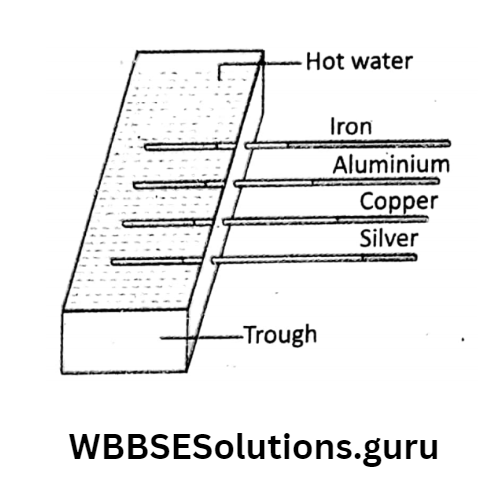
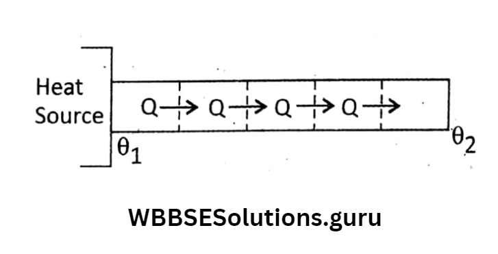
Measurement of thermal conductivity: The thermal conductivity of a solid is a measure of the ability of a conductor to conduct heat through it.

Let us take a rectangular conducting bar or a cylindrical block of a thickness (length) d and

area of cross-section A. If temperatures at two different faces (ends) are θand θ2 1 > θ2), then during steady-state heat flows

normally from the hotter face to the colder face. In the steady state it has been found from experiments that the amount of heat (Q) that flows in time f depends on the following factors:

  1. Area of cross-section (A),
  2. Thickness (d),
  3. The temperature difference between the faces (θ1 – θ2) and
  4. The time of heat conduction (t).
  5. Experimentally it is observed that
  6. Mathematically,

Where K is a constant of proportionality. The value of constant K depends on the nature of the substance.

It is called the coefficient of thermal conductivity or simply thermal conductivity. K is different for different substances.

Ex. for wood K is very low but for Cu, it is considerably high. For an ideal conductor, K is infinity and for an ideal insulator, K is zero. It is a characteristic property of the substance.

Definition: In the equation Thus, for a conducting slab of unit area of cross-section and unit thickness, if the temperature difference between its two sides is 1° then the amount of heat flow from the hot side to the cold side in unit time is called the thermal conductivity of the substance.

Physics Class 10 Wbbse

  1. Q α A,
  2. Q α 1/d,
  3. Q α (θ12)
  4. Q α t

⇒ \(\text { Mathematically, } Q \propto A \cdot \frac{\theta_1-\theta_2}{d} \cdot t \quad \text { or, } Q=K \cdot A \cdot \frac{\theta_1-\theta_2}{d} \cdot t\)

Where K is a constant of proportionality. The value of constant K depends on the nature of the substance.

It is called the coefficient of thermal conductivity or simply thermal conductivity. K is different for different substances.

Ex. for wood K is very low but for Cu, it is considerably high. For an ideal conductor, K is infinity and for an ideal insulator, K is zero. It is a characteristic property of the substance.

Definition: In the equation if A = 1, d = 1, (θX – θ2) = 1 and t = 1 then K= Q.

Thus, for a conducting slab of unit area of cross-section and unit thickness, if the temperature difference between its two sides is 1° then the amount of heat flow from the hot side to the cold side in unit time is called the thermal conductivity of the substance.

WBBSE Solutions For Class 10 Physical Science And Environment Chapter 4 Thermal Phenomena thermal conductivity.
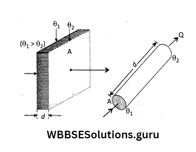
Units of K: \(\text { As } Q=K \cdot A \cdot \frac{\theta_1-\theta_2}{d} \cdot t \text {, so that } K=\frac{Q \cdot d}{A\left(\theta_1-\theta_2\right) t} \text {. }\)

In the CGS system: The common unit of thermal conductivity (K) is cal x cm

= \(\frac{\mathrm{cal} \times \mathrm{cm}}{\mathrm{cm}^2 \times{ }^{\circ} \mathrm{C} \times \mathrm{s}}=\mathrm{cal} \cdot \mathrm{cm}^{-1}{ }^{\circ} \mathrm{C}^{-1} \cdot \mathrm{s}^{-1}\)

In Sl system: The unit of K is \(=\frac{\mathrm{J} \times m}{m^2 \times \mathrm{K} \times \mathrm{s}}=\mathrm{J} \cdot \mathrm{m}^{-1} \mathrm{~K}^{-1} \cdot \mathrm{s}^{-1}\)

= \(\mathrm{W} \cdot \mathrm{m}^{-1} \mathrm{~K}^{-1}\left[\text { as } \mathrm{J} \cdot \mathrm{s}^{-1}=\mathrm{W}\right. \text { ] }\)

Heat current (H): It is the flow of heat in unit time through a conductor. From the relation

Q = \(K A \frac{\theta_1-\theta_2}{d}\) we find that heat current,

H \(=\frac{\mathrm{Q}}{t}=\dot{\mathrm{KA}} \frac{\theta_1-\theta_2}{d}\)

From this relation, it is seen that the heat current depends on:

1. Area of cross-section (A) and temperature difference (G1 – G2) and thickness or length (d).

Thermal resistivity and its analogy with electrical resistivity: We know that the ‘potential difference’ between two ends of a conductor regulates the electric current, similarly, the ‘temperature difference’ between two sides of a conductor regulates the flow of heat current.

According to Ohm’s law, electric current = Rate of flow of electric charge \(=\frac{\text { Potential difference }}{\text { Electric resistance }} \text {. }\)

If V1 and V2 are the electric potentials (V1 > V2) at two ends of a conductor of resistance of R, then electric current, \(\mathrm{I}=\frac{q}{t}=\frac{V_1-V_2}{\mathrm{R}} \ldots \ldots\)

We get the relation for heat current,  \(\mathrm{H}=\frac{\mathrm{Q}}{t}=K A \frac{\theta_1-\theta_2}{d}=\frac{\theta_1-\theta_2}{\frac{d}{K \Delta}}\)

Comparing (1) And (2) we see that the quality \(\frac{d}{K A}\)

is equivalent to resistance \(\mathrm{R}_{\mathrm{Th}}\left(=\frac{d}{\mathrm{KA}}\right)\)

and it is called thermal resistance again from the relation between electrical resistance (R) and resistivity

R = \(\frac{\rho d}{A}\) [d being the length or thickness of the conductor and comparing

R=\(\frac{\rho d}{A} \text { with } R_{\text {Th }}=\frac{d}{K A}\) we find the term

∴ \(\frac{1}{K}\) as thermal resistivity of the conductor.